|
|
| Author |
Message |
Ray White

Joined: 02 Dec 2014
Posts: 6308
Location: Derby
|
 Posted: Wed Apr 29, 2020 5:46 pm Post subject: Voltage regulatior with alternator Posted: Wed Apr 29, 2020 5:46 pm Post subject: Voltage regulatior with alternator |
 |
|
With the MG TC wiring I am starting completely from scratch. At present there is no wiring on the car although I have a new auto sparks loom ready to install.
What I would like to know is to do with voltage regulation. The old dynamo is being replaced by a 45 amp dynamator. (Looks like a dynamo and has a tacho attachment.) The system is 12 V (+ ground)
However, I have read that alternators have built in voltage regulation so I wondered if I should dispense with the original voltage regulator. Mine would need replacing in any event but the instructions show it being by passed but still earthed.
I appreciate there would still need to be a fuse box of some kind but if the old Lucas temperature compensated voltage regulator could be dispensed with altogether, it would free up a useful space on the bulkhead...
I hoping someone can help me with this unusual question. |
|
| Back to top |
|
 |
ukdave2002
Joined: 23 Nov 2007
Posts: 4104
Location: South Cheshire
|
| Posted: Thu Apr 30, 2020 7:37 am Post subject: |
|
|
Hi Ray
The original control box as well as housing the fuses is also a junction box, if you remove it you will have to join various cables some how, without the control box it will look less authentic.
A fuse box could also be used as the junction box, but I wouldn't think you will gain much space, unless you use inline fuse's?
Dave |
|
| Back to top |
|
|
alastairq
Joined: 14 Oct 2016
Posts: 1950
Location: East Yorkshire
|
| Posted: Thu Apr 30, 2020 10:04 am Post subject: |
|
|
| Quote: | | However, I have read that alternators have built in voltage regulation |
Not all alternators are so equipped.
Some alternators will have built-in diode packs and regulators...others need separate ditto.
Best consult with vendors?
_________________
Dellow Mk2, 1951 built, reg 1952.
Fiat 126 BIS
Cannon special [1996 registered. Built in 1950's]
----------------------------------------------
Ford Pop chassis, Ashley 1172 bodyshell, in pieces. |
|
| Back to top |
|
|
ukdave2002
Joined: 23 Nov 2007
Posts: 4104
Location: South Cheshire
|
| Posted: Thu Apr 30, 2020 10:42 am Post subject: |
|
|
| alastairq wrote: | | Quote: | | However, I have read that alternators have built in voltage regulation |
Not all alternators are so equipped.
Some alternators will have built-in diode packs and regulators...others need separate ditto.
Best consult with vendors? |
Ray is fitting a Dynamotor, so the rectification and regulation will be built in.
Dave |
|
| Back to top |
|
|
colwyn500
Joined: 21 Oct 2012
Posts: 1745
Location: Nairn, Scotland
|
| Posted: Thu Apr 30, 2020 5:50 pm Post subject: |
|
|
In the case of our little Fiat 500's, when changing to an alternator we keep the regulator box, having first removed the innards. Then the terminals can be used as the connection points for the wiring from the alternator. You will have an existing thick wire on terminal 30 which finds its way to the battery and you connect this to a cable from the main + terminal on the alternator. There should also be a smaller gauge wire from the alternator which connects to the wire from the ignition warning light. The old wires from the dynamo are not needed and can be taped up.
As you have a new loom, I'm not sure if this comes modified for an alternator already. So to summarise...big wire to battery, small wire to IGW. You won't regret the modification.  |
|
| Back to top |
|
|
Ray White
Joined: 02 Dec 2014
Posts: 6308
Location: Derby
|
| Posted: Sat May 02, 2020 1:02 am Post subject: |
|
|
Thanks for the replies. I mentioned earlier that the directions for installing the Dynamator show the original regulator is effectively by passed but it can be used as an earthing point and fused junction box if required. At present I am undecided.
The regulator that came with the car has a broken cover but I expect used ones are available. The wiring loom is taking the 45 amp alternator into account - as is the guy who is rebuilding the ammeter. |
|
| Back to top |
|
|
Ray White
Joined: 02 Dec 2014
Posts: 6308
Location: Derby
|
| Posted: Sun Jun 21, 2020 10:58 am Post subject: |
|
|
I have decided to keep the voltage regulator in place. It is in good condition and I have repaired the casing so it looks good. I don't want to do anything that will damage the instrument (it must be reversible) but I do need to modify it for use with the Dynamater...
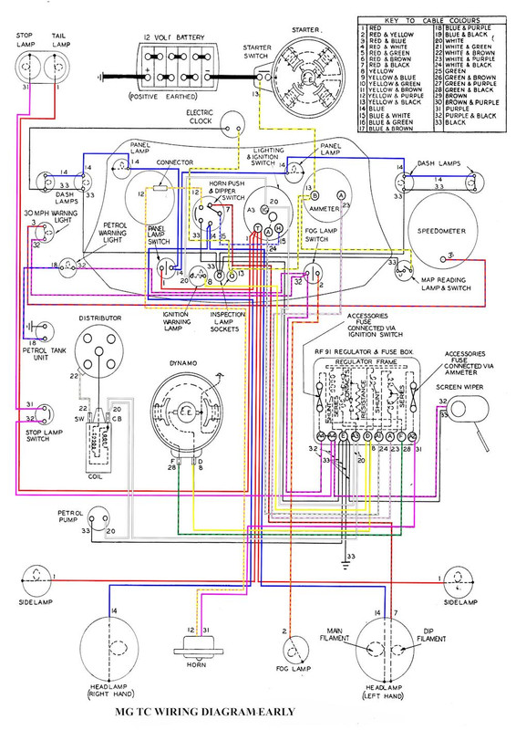
I have a coloured wiring diagram that is helpful in showing which wires go to and from it but I am not at all certain how best to by pass the voltage regulation part and keep the terminals and fuses in use.
Please advise.

 |
|
| Back to top |
|
|
Peter_L
Joined: 10 Apr 2008
Posts: 2680
Location: New Brunswick. Canada.
|
| Posted: Sun Jun 21, 2020 5:42 pm Post subject: |
|
|
| Interesting to see the 30mph warning light switched from the speedo. |
|
| Back to top |
|
|
DM

Joined: 21 Dec 2008
Posts: 212
Location: North Cornwall
|
| Posted: Sun Jun 21, 2020 5:49 pm Post subject: |
|
|
Add the warning light relay as per the instructions with the Dynamator
http://www.accuspark.co.uk/InstructionsPDF/Dynamator%20Positive%20Earth%20Instructions.pdf
If you mount the relay behind the instrument panel it will make life easier.
I am assuming the wiring harness is standard apart from cable sizes beefed up to cope with the inceased output of the Dynamotor.
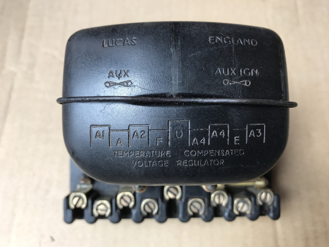
On the regulator remove the yellow warning light wire from teminal D and the purple wire from the F terminal, link them together this will use the old dynamo fiels wire as the warning light feed. There will now be no wires connected to the D and F terminals on the regulator.
Take your output from the Dynamator to Terminal A on the regulator and add a thick link wire betwen terminals A and A1.The wire link added makes sure you dont put the high output current from the new alternator through the coils inside the old regulator.
Have an isolating switch in line with the battery just in case something goes adrift. |
|
| Back to top |
|
|
Ray White
Joined: 02 Dec 2014
Posts: 6308
Location: Derby
|
| Posted: Sun Jun 21, 2020 7:17 pm Post subject: |
|
|
| DM wrote: | Add the warning light relay as per the instructions with the Dynamator
http://www.accuspark.co.uk/InstructionsPDF/Dynamator%20Positive%20Earth%20Instructions.pdf
If you mount the relay behind the instrument panel it will make life easier.
I am assuming the wiring harness is standard apart from cable sizes beefed up to cope with the inceased output of the Dynamotor.
On the regulator remove the yellow warning light wire from teminal D and the purple wire from the F terminal, link them together this will use the old dynamo fiels wire as the warning light feed. There will now be no wires connected to the D and F terminals on the regulator.
Take your output from the Dynamator to Terminal A on the regulator and add a thick link wire betwen terminals A and A1.The wire link added makes sure you dont put the high output current from the new alternator through the coils inside the old regulator.
Have an isolating switch in line with the battery just in case something goes adrift. |
Hello DM. Thank you for responding so quickly and clearly. I have not fully installed the wiring yet as I am still awaiting the body (and dashboard) so the voltage regulator is still on the bench. With your advise I hope it will go together properly.
I appreciate you helping me with the instructions and have located the relay. I also have the heavier wire to go to the ammeter which has been rebuilt to handle a 45 amp load.
I have been told not to attach any other wires to it so where the starter motor wire should go now I don't know.? |
|
| Back to top |
|
|
Ray White
Joined: 02 Dec 2014
Posts: 6308
Location: Derby
|
| Posted: Sun Jun 21, 2020 7:33 pm Post subject: |
|
|
| Peter_L wrote: | | Interesting to see the 30mph warning light switched from the speedo. |
Hi Peter. As it happens, in 1949 my MG TC was originally exported new to Australia where the speed limit had yet to be introduced - so the "thirtylight" was not fitted to one of the chrome plated map reading lamps on the dashboard. I have just had the speedo restored and the mechanism was missing from the instrument.
This means the map reading lights on my car's dashboard will be (and always were) identical.
...So what? you may ask. Well, it will give the cognoscenti something to think about when giving me a hard time for all my upgrades! |
|
| Back to top |
|
|
DM
Joined: 21 Dec 2008
Posts: 212
Location: North Cornwall
|
| Posted: Sun Jun 21, 2020 7:47 pm Post subject: |
|
|
Your main battery cable will go to the starter motor solenoid, a smaller wire which will be in your new loom will go from the solenoid to the ammeter exactly as it was wired on the original starter.
Your new starter switch will only have to supply the solenoid current and not the starter motor current so the switch and wiring for that does not have to be so heavy.
You could fit something like this in place of the cable system -
https://www.qtponline.com/products/starter-switch-case-ihc-51530.html?filter_set[]=1093,1117,1287,4473 |
|
| Back to top |
|
|
Ray White
Joined: 02 Dec 2014
Posts: 6308
Location: Derby
|
| Posted: Sun Jun 21, 2020 10:26 pm Post subject: |
|
|
This little object is known in MG circles as the "mousetrap". It is mounted on the edge of the bulkhead and funnels three cables to 1) the starter 2) the choke... and 3) the slow running adjustment - otherwise known as a hand throttle.
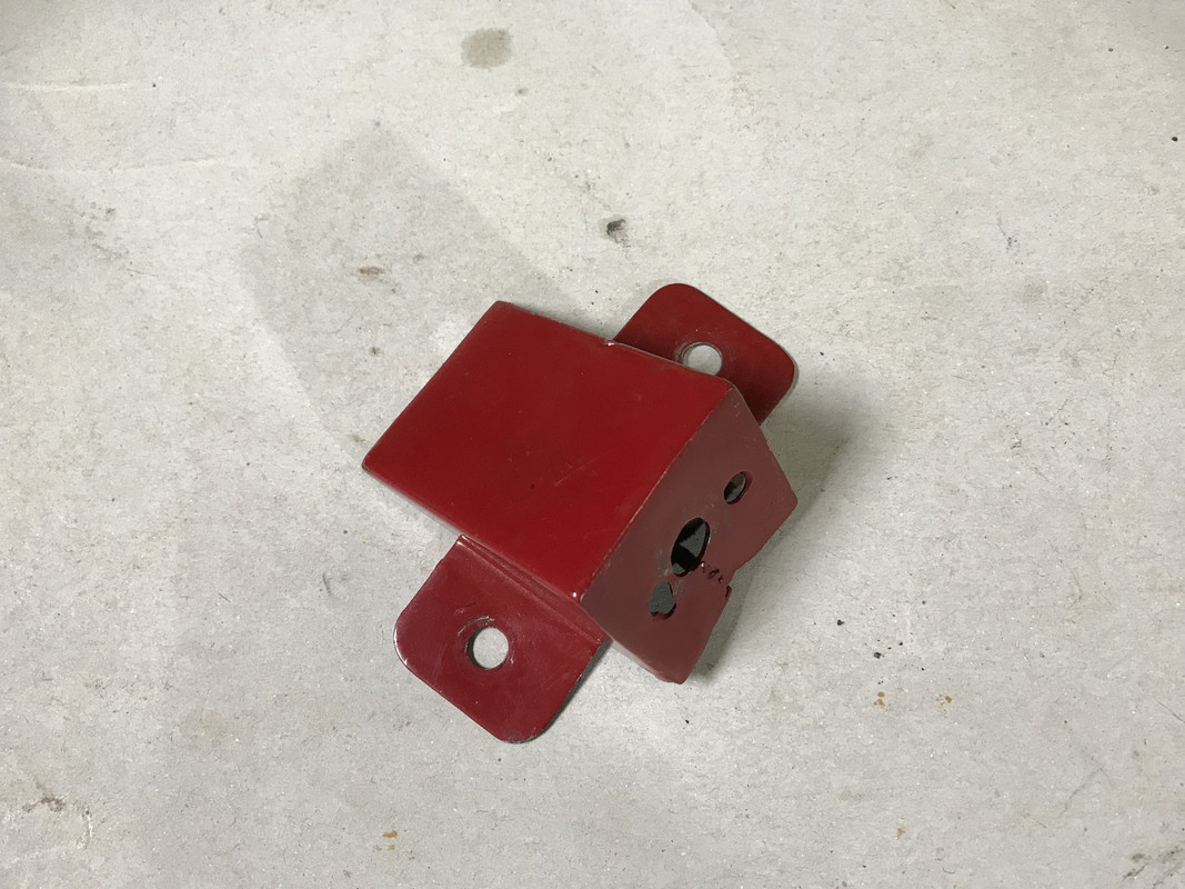
Since fitting a new high torque starter motor I have no need for such a long starter cable and as the supercharger carburettor is mounted fore/aft (as opposed to side to side on the engine) I can no longer use the other two cables either.
My solution is to mount a new starter switch onto the front of the mousetrap and attach a shorter cable to the dashboard; thus retaining the original starter knob.
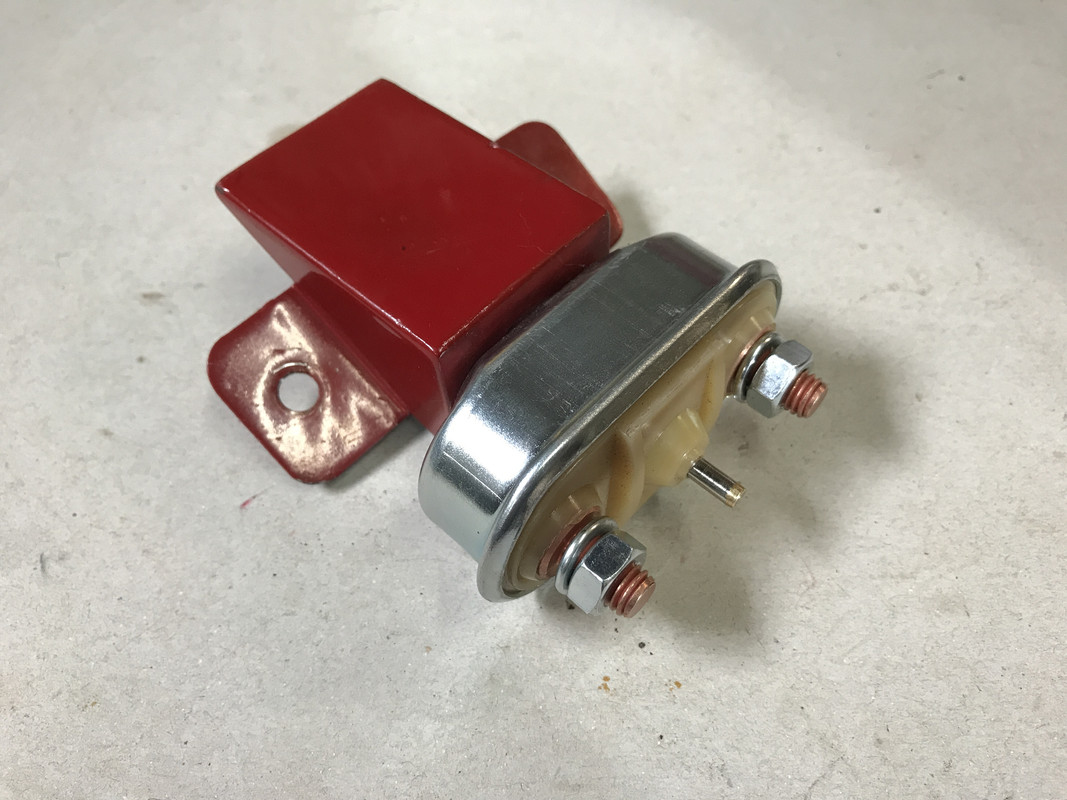
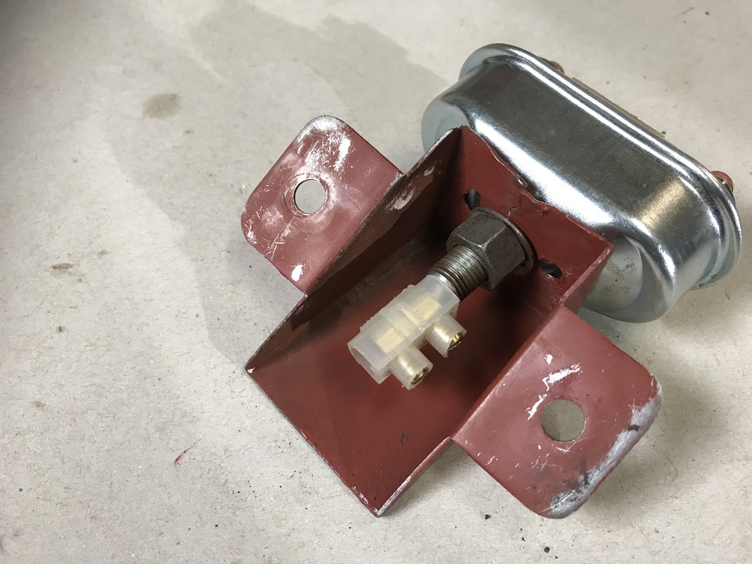
As the other two cables need to approach the new carb from a different direction, I can send them directly through the bulkhead with very little alteration and also retaining the original layout. |
|
| Back to top |
|
|
Ray White
Joined: 02 Dec 2014
Posts: 6308
Location: Derby
|
| Posted: Mon Jun 22, 2020 3:31 pm Post subject: |
|
|
I have received this information from the instruments specialist.
"........on an original BM ammeter with the shielded grub screws there is only room for the larger alternator size cables. what We have converted with a 50 amp shunt inside is based on a similar Lucas ammeter. The ones we do for Jagaur XK120/150 have terminals for just the one in and one out wire..."
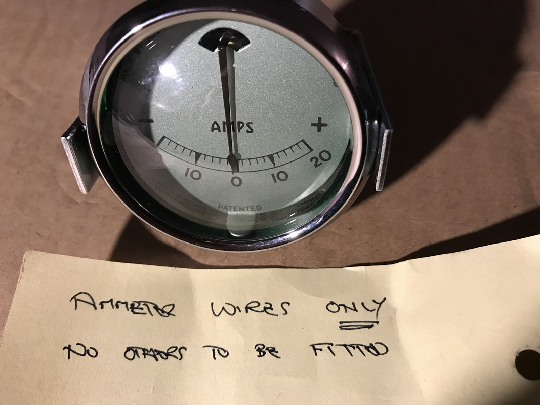
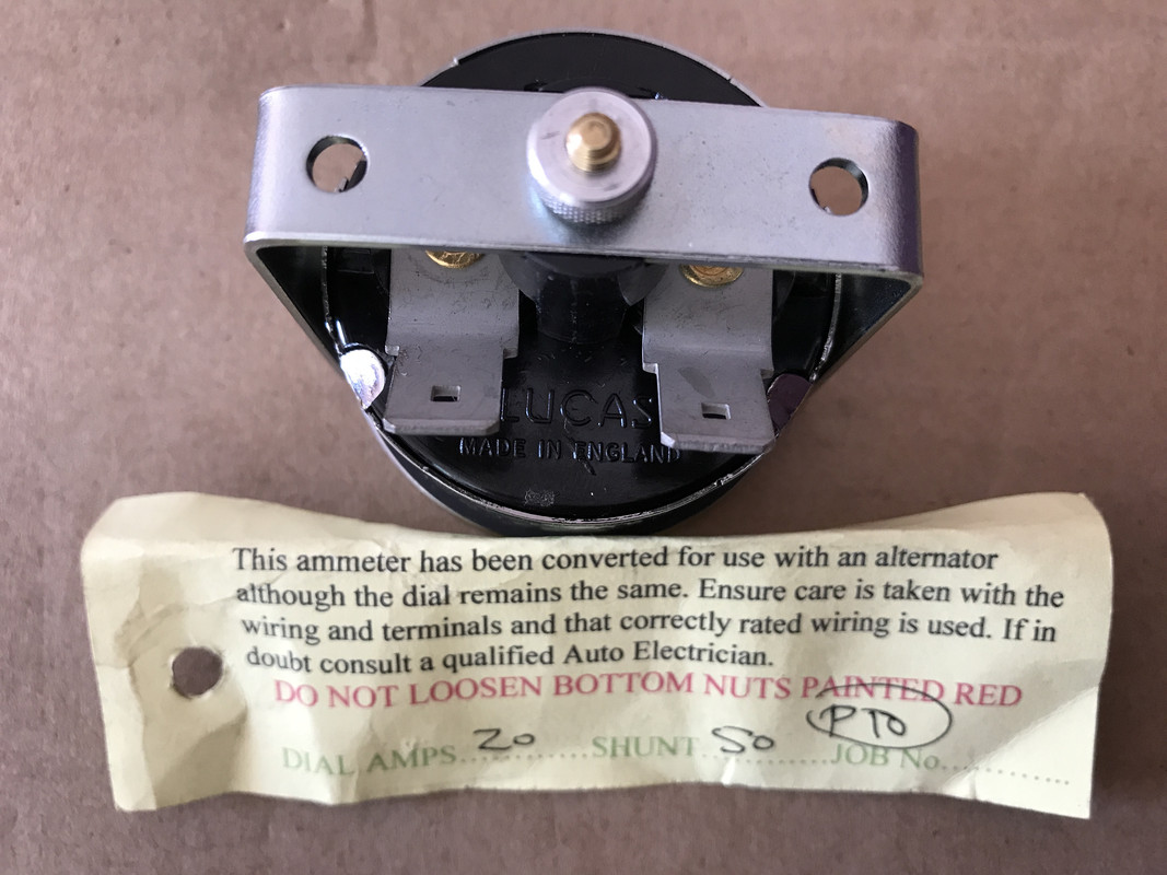
I am not sure where the starter solenoid wire should go to if it won't fit on the ammeter. |
|
| Back to top |
|
|
alastairq
Joined: 14 Oct 2016
Posts: 1950
Location: East Yorkshire
|
| Posted: Mon Jun 22, 2020 5:43 pm Post subject: |
|
|
Piggyback?
_________________
Dellow Mk2, 1951 built, reg 1952.
Fiat 126 BIS
Cannon special [1996 registered. Built in 1950's]
----------------------------------------------
Ford Pop chassis, Ashley 1172 bodyshell, in pieces. |
|
| Back to top |
|
|
|


