|
|
| Author |
Message |
Ray White

Joined: 02 Dec 2014
Posts: 6310
Location: Derby
|
 Posted: Mon Jan 11, 2021 3:38 pm Post subject: Lucas RF 95 voltage regulator modification. Posted: Mon Jan 11, 2021 3:38 pm Post subject: Lucas RF 95 voltage regulator modification. |
 |
|
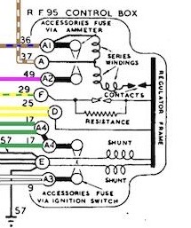
As I now have an alternator with voltage regulation I no longer need the RF 95 but I would still like to retain it and use the fuses and terminals as before.
I could leave the D and F terminals blank but can I still connect the input from the ammeter at terminal A?
Would it be possible to avoid the coils and contacts but still have an earth?
I don't want to destroy the instrument as I would like, if possible, to be able to still use it with a dynamo should the need arise.
 |
|
| Back to top |
|
 |
DM

Joined: 21 Dec 2008
Posts: 212
Location: North Cornwall
|
 Posted: Mon Jan 18, 2021 9:08 am Post subject: Posted: Mon Jan 18, 2021 9:08 am Post subject: |
 |
|
Hi Ray,
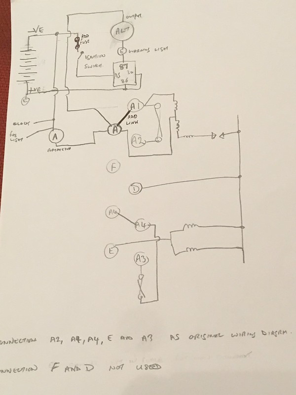
Will post a drawing of how to leave the regulator in place as a junction/fuse box with the alternator set up later today when I get back from work.
Dennis |
|
| Back to top |
|
 |
Ray White

Joined: 02 Dec 2014
Posts: 6310
Location: Derby
|
 Posted: Mon Jan 18, 2021 6:59 pm Post subject: Posted: Mon Jan 18, 2021 6:59 pm Post subject: |
 |
|
The 5 pin (changeover) relays that I have bought have a diode across the coil to protect valuable electronics from stray voltage spikes.
The question I have relates to the positive earth alternator - or Dynamater - which instructs that the ignition warning light must be wired through the supplied relay. The Stealth Dynamater fitting instructions have a wiring diagram showing terminals 30 and 86 externally connected and both earthed.
The 4 pin relay (as supplied) has a wire connecting these two terminals which I presume is how I should assemble the relay holder.
However, I understand that the relay with a diode that I prefer to use must have terminal 86 connected to a 12 volt supply. with 85 connected to ground. Failure to do this can damage the diode.
If I do use the changeover relay and wire it with 85 grounded, am I right in thinking I should I still attach the other end of the linking wire to terminal 30? |
|
| Back to top |
|
 |
ukdave2002
Joined: 23 Nov 2007
Posts: 4104
Location: South Cheshire
|
 Posted: Mon Jan 18, 2021 7:16 pm Post subject: Posted: Mon Jan 18, 2021 7:16 pm Post subject: |
 |
|
Hi Ray
I don't know what the pin numbers relate to, all you need to do is make sure the relay diode has the "band" end on the +ve side of the circuit, otherwise it will be a short circuit.
Dave |
|
| Back to top |
|
 |
Ray White

Joined: 02 Dec 2014
Posts: 6310
Location: Derby
|
 Posted: Mon Jan 18, 2021 8:13 pm Post subject: Posted: Mon Jan 18, 2021 8:13 pm Post subject: |
 |
|
| ukdave2002 wrote: | Hi Ray
I don't know what the pin numbers relate to, all you need to do is make sure the relay diode has the "band" end on the +ve side of the circuit, otherwise it will be a short circuit.
Dave |
'
I see no sign on the relay where a 'band' might be. |
|
| Back to top |
|
 |
Penman
Joined: 23 Nov 2007
Posts: 4756
Location: Swindon, Wilts.
|
 Posted: Mon Jan 18, 2021 9:05 pm Post subject: Posted: Mon Jan 18, 2021 9:05 pm Post subject: |
 |
|
Hi
The band would be on the diode. Silver on this one.

_________________
Bristols should always come in pairs.
Any 2 from:-
Straight 6
V8 V10 |
|
| Back to top |
|
 |
DM

Joined: 21 Dec 2008
Posts: 212
Location: North Cornwall
|
 Posted: Mon Jan 18, 2021 9:12 pm Post subject: Posted: Mon Jan 18, 2021 9:12 pm Post subject: |
 |
|
The diode symbol is the arrow with a bar across the pointed end that you can see on the casing of the relay, that bar is the band dave refers to.
If you connect as this diagram you should be right.
 |
|
| Back to top |
|
 |
Ray White

Joined: 02 Dec 2014
Posts: 6310
Location: Derby
|
 Posted: Mon Jan 18, 2021 11:37 pm Post subject: Posted: Mon Jan 18, 2021 11:37 pm Post subject: |
 |
|
The worry I have is that the diode could be damaged if the relay is not earthed at terminal 85 with 12v going to 86.
Its in bold letters here:
(scroll down to relay configurations and types...)
https://www.12voltplanet.co.uk/relay-guide.html |
|
| Back to top |
|
 |
DM

Joined: 21 Dec 2008
Posts: 212
Location: North Cornwall
|
 Posted: Tue Jan 19, 2021 8:39 am Post subject: Posted: Tue Jan 19, 2021 8:39 am Post subject: |
 |
|
That write up is for -ve earth, when you change to +ve earth you have to reverse the relay coil connections to suit.
Relay coil connection 86 must be supplied from the battery +ve to avoid damaging the diode. |
|
| Back to top |
|
 |
Ray White

Joined: 02 Dec 2014
Posts: 6310
Location: Derby
|
 Posted: Tue Jan 19, 2021 10:53 am Post subject: Posted: Tue Jan 19, 2021 10:53 am Post subject: |
 |
|
| DM wrote: | That write up is for -ve earth, when you change to +ve earth you have to reverse the relay coil connections to suit.
Relay coil connection 86 must be supplied from the battery +ve to avoid damaging the diode. |
Thank you for that. I will now be happy to crack on with it. |
|
| Back to top |
|
 |
ukdave2002
Joined: 23 Nov 2007
Posts: 4104
Location: South Cheshire
|
 Posted: Tue Jan 19, 2021 1:59 pm Post subject: Posted: Tue Jan 19, 2021 1:59 pm Post subject: |
 |
|
If you do damage the diode its not the end of the world, a 1N4148 which is the diode we used to use in school projects across relay coils will set you back about 5p  |
|
| Back to top |
|
 |
Ray White

Joined: 02 Dec 2014
Posts: 6310
Location: Derby
|
 Posted: Tue Jan 19, 2021 3:14 pm Post subject: Posted: Tue Jan 19, 2021 3:14 pm Post subject: |
 |
|
| ukdave2002 wrote: | If you do damage the diode its not the end of the world, a 1N4148 which is the diode we used to use in school projects across relay coils will set you back about 5p  |
I have planned for armageddon. I bought 8 relays "just in case".  |
|
| Back to top |
|
 |
ukdave2002
Joined: 23 Nov 2007
Posts: 4104
Location: South Cheshire
|
 Posted: Tue Jan 19, 2021 7:50 pm Post subject: Posted: Tue Jan 19, 2021 7:50 pm Post subject: |
 |
|
| Ray White wrote: | | ukdave2002 wrote: | If you do damage the diode its not the end of the world, a 1N4148 which is the diode we used to use in school projects across relay coils will set you back about 5p  |
I have planned for armageddon. I bought 8 relays "just in case".  |
Belt & braces  |
|
| Back to top |
|
 |
Ray White

Joined: 02 Dec 2014
Posts: 6310
Location: Derby
|
 Posted: Tue Jan 19, 2021 9:36 pm Post subject: Posted: Tue Jan 19, 2021 9:36 pm Post subject: |
 |
|
So far... so good. 
I now have the small alternator / warning light wire passing through a relay and a fuse ready to connect to the ignition switch at IG.
Looking at the wiring diagram I see that the ignition switch has power supplied from the ammeter at 'A' . I am keen to protect this delicate and expensive switch as much as possible so I am hoping a relay will be the answer.
I have a neat relay holder which can house 4 relays and so far I have organised a common + earth to all the No.86 terminals. The alternator relay also has T30 linked to T86.
I am happy that the connection to the steel battery box is an excellent + earth.
The next relay therefore has terminals 30, 87 and 85 remaining to be wired up. I assume that T85 will go to 'A' on the ignition switch via a fuse.
What I am less sure about is what to do with T30 and T87 on the relay. I presume a - 12 volt supply is required but that is about the extent of my understanding... |
|
| Back to top |
|
 |
DM

Joined: 21 Dec 2008
Posts: 212
Location: North Cornwall
|
 Posted: Tue Jan 19, 2021 11:30 pm Post subject: Posted: Tue Jan 19, 2021 11:30 pm Post subject: |
 |
|
 |
|
| Back to top |
|
 |
|
