|
|
| Author |
Message |
Ray White

Joined: 02 Dec 2014
Posts: 6312
Location: Derby
|
 Posted: Mon Jan 25, 2021 11:13 am Post subject: which connector? Posted: Mon Jan 25, 2021 11:13 am Post subject: which connector? |
 |
|
A simple question.
Should the wire connecting a switch to a relay be connected to the input or the output terminal on the back of a switch? |
|
| Back to top |
|
 |
ukdave2002
Joined: 23 Nov 2007
Posts: 4104
Location: South Cheshire
|
| Posted: Mon Jan 25, 2021 1:38 pm Post subject: |
|
|
| The output as you are using it to switch the relay "on" |
|
| Back to top |
|
|
Ray White
Joined: 02 Dec 2014
Posts: 6312
Location: Derby
|
| Posted: Mon Jan 25, 2021 1:59 pm Post subject: |
|
|
| Thank you Dave. If the output switches the relay on what does the fused 12 v wire from the battery do? |
|
| Back to top |
|
|
ukdave2002
Joined: 23 Nov 2007
Posts: 4104
Location: South Cheshire
|
| Posted: Mon Jan 25, 2021 2:03 pm Post subject: |
|
|
If for example you were fitting a relay in a headlamp circuit:
The existing live headlamp wire connects to both the headlamp switch and pin 30 on the relay, or if you are using a separate fused supply from the battery connect this to pin 30, but I'd be tempted to use the original feed for simplicity.
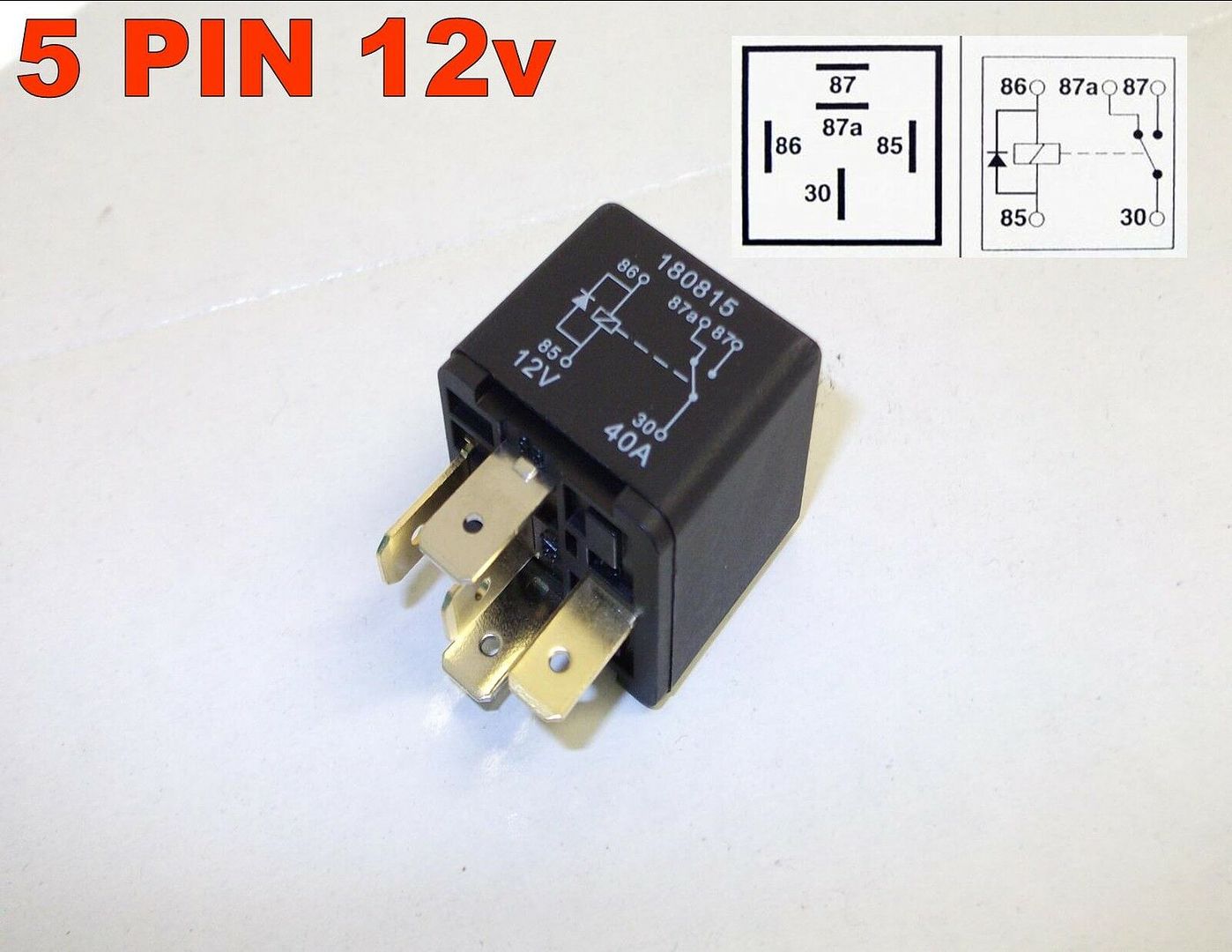
The output from the switch conects to pin 85 on the relay if the vehicle is + earth or pin 86 if -ve earth. (this is because of the diode)
For a +ve earth vehicle; pin 86 conects to earth, for a -ve earth vehicle pin 85 conects to earth
The wire that was originally connected to the output of the switch now connects to pin 87.
Most relays are marked like the one below, clearly indicating the diode polarity and the contacts. This particular relay is a change over relay so has an additional contact 87a
Hope this helps
Dave |
|
| Back to top |
|
|
Ray White
Joined: 02 Dec 2014
Posts: 6312
Location: Derby
|
| Posted: Mon Jan 25, 2021 2:34 pm Post subject: |
|
|
Sorry Dave. I am confused because you have said the existing live headlamp wire connects to both the headlamp switch and pin 30 ...
....but then you go on to say the output from the switch connects to pin 85 on the relay..
I do understand that + earth like mine has 86 for earth. That is how I am doing it. What I don't understand is how the output from the switch can go to 30 AND 85.?? |
|
| Back to top |
|
|
alastairq
Joined: 14 Oct 2016
Posts: 1953
Location: East Yorkshire
|
| Posted: Mon Jan 25, 2021 4:24 pm Post subject: |
|
|
| Quote: | | What I don't understand is how the output from the switch can go to 30 AND 85.?? |
You'll need a live supply to the switch, in order to [eventually] operate the relay itself.
Effectively, this is a ''separate'' supply to that of the headlamps. But, and will be, the 'same' supply, or 'source' of 12 volts.
The circuit through the dash switch will be separate to the circuit through the relay to the headlamps..
The source of 12 volts will be the same, however, for both.
_________________
Dellow Mk2, 1951 built, reg 1952.
Fiat 126 BIS
Cannon special [1996 registered. Built in 1950's]
----------------------------------------------
Ford Pop chassis, Ashley 1172 bodyshell, in pieces. |
|
| Back to top |
|
|
Ray White
Joined: 02 Dec 2014
Posts: 6312
Location: Derby
|
| Posted: Mon Jan 25, 2021 4:44 pm Post subject: |
|
|
AHHH!  |
|
| Back to top |
|
|
Ray White
Joined: 02 Dec 2014
Posts: 6312
Location: Derby
|
| Posted: Mon Jan 25, 2021 5:52 pm Post subject: |
|
|
| If a wire has a fuse at it's terminal (like on the deactivated RF95) is it still "fused" ...or does the current need to flow through and out the other side of the fuse? |
|
| Back to top |
|
|
Ray White
Joined: 02 Dec 2014
Posts: 6312
Location: Derby
|
| Posted: Mon Jan 25, 2021 6:36 pm Post subject: |
|
|
| ukdave2002 wrote: | If for example you were fitting a relay in a headlamp circuit:
The existing live headlamp wire connects to both the headlamp switch and pin 30 on the relay, or if you are using a separate fused supply from the battery connect this to pin 30, but I'd be tempted to use the original feed for simplicity.
The output from the switch conects to pin 85 on the relay if the vehicle is + earth or pin 86 if -ve earth. (this is because of the diode)
For a +ve earth vehicle; pin 86 conects to earth, for a -ve earth vehicle pin 85 conects to earth
The wire that was originally connected to the output of the switch now connects to pin 87.
Most relays are marked like the one below, clearly indicating the diode polarity and the contacts. This particular relay is a change over relay so has an additional contact 87a
Hope this helps
Dave |
I don't have ANY original wiring, lights or instruments installed; not even a dashboard - so I am trying to do as much as I can with the new wiring harness ( including relays and fuses for safety mainly) while I wait for the new body and dashboard to arrive. |
|
| Back to top |
|
|
ukdave2002
Joined: 23 Nov 2007
Posts: 4104
Location: South Cheshire
|
| Posted: Mon Jan 25, 2021 7:27 pm Post subject: |
|
|
| Ray White wrote: | | ukdave2002 wrote: | If for example you were fitting a relay in a headlamp circuit:
The existing live headlamp wire connects to both the headlamp switch and pin 30 on the relay, or if you are using a separate fused supply from the battery connect this to pin 30, but I'd be tempted to use the original feed for simplicity.
The output from the switch conects to pin 85 on the relay if the vehicle is + earth or pin 86 if -ve earth. (this is because of the diode)
For a +ve earth vehicle; pin 86 conects to earth, for a -ve earth vehicle pin 85 conects to earth
The wire that was originally connected to the output of the switch now connects to pin 87.
Most relays are marked like the one below, clearly indicating the diode polarity and the contacts. This particular relay is a change over relay so has an additional contact 87a
Hope this helps
Dave |
I don't have ANY original wiring, lights or instruments installed; not even a dashboard - so I am trying to do as much as I can with the new wiring harness ( including relays and fuses for safety mainly) while I wait for the new body and dashboard to arrive. |
Understand, so is this question to help determine the spec you need to give to the harness supplier, or have you got a standard harness that needs to accommodate the changes? |
|
| Back to top |
|
|
Ray White
Joined: 02 Dec 2014
Posts: 6312
Location: Derby
|
| Posted: Mon Jan 25, 2021 8:43 pm Post subject: |
|
|
[quote="ukdave2002"] | Ray White wrote: | | ukdave2002 wrote: |
I don't have ANY original wiring, lights or instruments installed; not even a dashboard - so I am trying to do as much as I can with the new wiring harness ( including relays and fuses for safety mainly) while I wait for the new body and dashboard to arrive. |
Understand, so is this question to help determine the spec you need to give to the harness supplier, or have you got a standard harness that needs to accommodate the changes? |
[Please bear with me Dave. I am attempting to make up for years of handing all electrical issues to my late Father in Law who was a time served auto electrician. In fact, probably because he had as little confidence in my abilities as I have in myself he would insist in being consulted and then he would take charge and quickly sort whatever the problem was.]
To date I have installed a new TC loom in the chassis and bulkhead. I requested that the wiring should be suitable for an alternator and I have fitted a 45 amp wire from the alternator to battery. (starter switch actually).
As requested, a reversing light wire and indicator wires have been included (a switch is fitted to the T9 gearbox).
Fortunately the loom has been updated with TWO dipped headlamp wires but regrettably (because I hadn't noticed it) still only one tail/stop light is included as per the wiring schematic. I have subsequently bought extra wiring for the second D lamp so not a problem.
The other changes such as extra fuses and relays is as a result of mission creep. I am trying to get to grips with developments in auto electrics that have left the original specification looking somewhat inadequate. For example; it would seem that all MGs (along with most other manufacturers) from the mid 'Seventies onwards protected their ignition systems with a relay. The high failure rate of expensive switches these days means that an upgrade such as this looks to me like a sensible option. Other switches - some of considerable age - also seem vulnerable and with heavier loads ( lights etc.) the addition of relays in a modified car seem logical to me. |
|
| Back to top |
|
|
Ray White
Joined: 02 Dec 2014
Posts: 6312
Location: Derby
|
| Posted: Mon Jan 25, 2021 11:48 pm Post subject: |
|
|
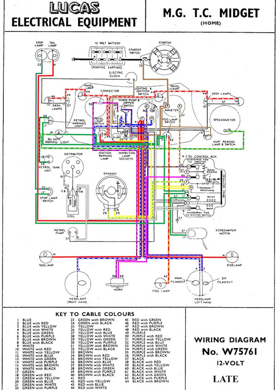
With reference to the above wiring diagram...
To instal a relay (changeover with diode) into the headlamp circuit should I...
take a wire from terminal A1 on the de activated RF95 to 30 on the relay?
disconnect the blue wire from H and connect it to 85 ?
connect a wire from 87 to H on the switch ?
86 = + earth. |
|
| Back to top |
|
|
ukdave2002
Joined: 23 Nov 2007
Posts: 4104
Location: South Cheshire
|
| Posted: Tue Jan 26, 2021 11:50 am Post subject: |
|
|
| Ray White wrote: |
Hi Ray, see answers in red
With reference to the above wiring diagram...
To instal a relay (changeover with diode) into the headlamp circuit should I...
take a wire from terminal A1 on the de activated RF95 to 30 on the relay? Yes, as this is a fused supply, conveniently you can pick it up from "A" on the Ignition /lamp switch, rather than run a new cable to A1.
disconnect the blue wire from H and connect it to 85 ? No; leave it connected to "H" cut the blue wire and connect 85 to "H" , connect the other end to 87 this will then go to "2" on the dip switch (originally the blue wire would go directly from H on the ignition light switch to 2 on the dip switch)
connect a wire from 87 to H on the switch ? No see above
86 = + earth. Correct
87a on the relay is not used as you are not using the relay as a change over relay. This will protect the Ignition/ lamp switch contacts, the dip switch will still be switching the full load, if you want to protect the dip switch as well, you will need 2 relays (one for main and one for dip) and fit them on the "output "side of the dip switch, this will then protect all switches in the head lamp circuit.
A tip when dealing with electrics is to draw the circuit, its far easier to get you head round a drawing than visualise it in your head!
|
|
|
| Back to top |
|
|
Ray White
Joined: 02 Dec 2014
Posts: 6312
Location: Derby
|
| Posted: Tue Jan 26, 2021 12:44 pm Post subject: |
|
|
Many thanks for your help Dave.
I am rubbish at drawing. I must practice more but after throwing half a dozen attempts in the bin (with some frustration!) I tend to give up.!
That said; I think (or hope) I am getting somewhere at last. I will want to fit a relay to cover the old dip switch.
Once I have mastered it I am sure I will wonder what all the fuss was about! 
P.S. 1( Which wire from the relay has the fuse?
and 2) can the fuse be at the end of a wire or does the current have to go through it and onto something else?? |
|
| Back to top |
|
|
ukdave2002
Joined: 23 Nov 2007
Posts: 4104
Location: South Cheshire
|
| Posted: Wed Jan 27, 2021 10:17 am Post subject: |
|
|
| Ray White wrote: |
P.S. 1( Which wire from the relay has the fuse?
and 2) can the fuse be at the end of a wire or does the current have to go through it and onto something else?? |
The fuse in the RF95 will protect all the headlamp wiring in the example above. Fuses should be as electrically close to the source of power as they can only protect against faults "north" of its "output"
Dave |
|
| Back to top |
|
|
|


