Autovac Manufacturing Company.
This small booklet was published by the Autovac Manufacturing Company Ltd, of Heaton Norris in Stockport, during the 1920s. In addition to being fitted some vintage cars of the era, Autovac vacuum-operated fuel systems were often to be found on commercial vehicles, usually buses and coaches. The text within the booklet explains the principles of how the Autovac system works, and gives tips and advice on its maintenance.
|
|
|
The basics of the system are described as thus:
|
|
"The Patent Autovac Vacuum Petrol Feed Apparatus (Higginson, Arundel & Jay's Patent) has for its object the elevation of fuel from a main tank placed below the level of the carburetter, thereby gaining the advantages of accessibility, increased fuel capacity, and correct weight distribution.
|
|
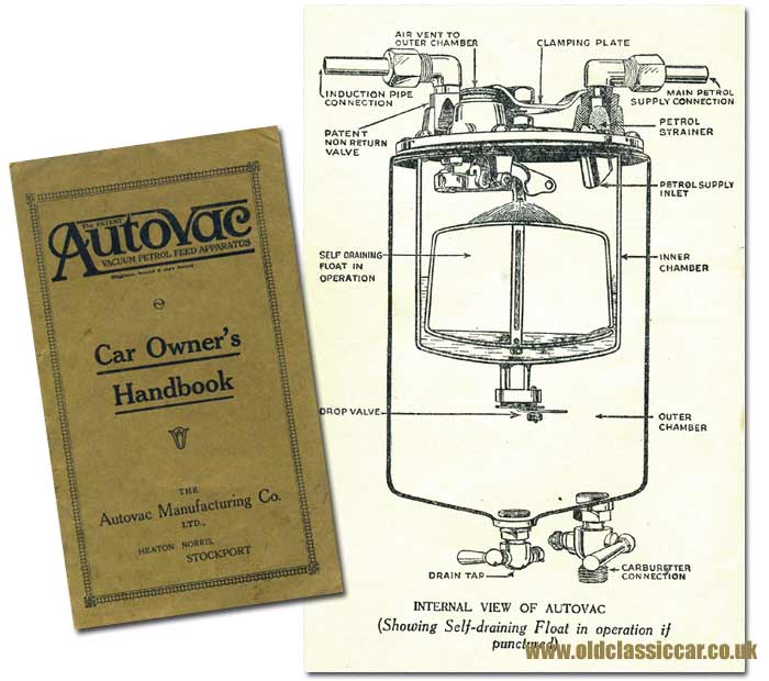
The system employs a small auxiliary tank usually mounted on the engine side of the dashboard, with its base above the carburetter float chamber. It is divided into two chambers - the inner or vacuum chamber being connected to the induction pipe and main petrol tank, and the lower or reserve chamber to the carburetter. Communication between the two is via the drop valve at the base of the inner chamber.
|
|
The engine suction creates a partial vacuum in the upper chamber, thus closing the drop valve and drawing up petrol from the main tank. As the fuel flows in, the float rises. When it reaches a certain height two valves are operated - one cuts off the suction, the other admits air; this admission of air destroys the vacuum, releases the drop valve, and allows the petrol to flow into the outer chamber. As the reserve chamber is always open to the atmosphere through the air vent, the fuel flows to the carburetter by gravity.
|
|
As the float falls with the outflow of fuel from the inner chamber, the valve mechanism is again actuated and the operation of taking in fuel is repeated."
|
Faults with Autovac operation.
According to the leaflet, most faults that the firm heard about related to blockages caused by foreign matter in the fuel. To ward off potential problems of this kind, they recommended regular cleaning of the filter. A sediment trap was also built in to the base of the unit, simply opening the tap and draining off any sediment and water was again recommended as a routine task. Tweaking all the joints in the system was also recommended, especially those used in the vacuum part of the Autovac system. A patented self-draining float was employed, details of which are given:
|
|
"Among the many improvements embodied in the design of the Autovac Apparatus, this is probably the most important. A hollow float stem is used, having a hole inside and one outside the body of the main float. Any petrol entering the float is automatically evacuated through the stem during the suction period, and during the period of atmospheric pressure air flows in, thereby enabling the float to function as when air-tight.
|
Fitting an Autovac.
"The best position for the Autovac is on the Engine side of the dashboard; if this is not convenient it can be fitted on the driver's side, or on suitable brackets fixed to the induction pipe or cylinder block.
|
|
The petrol flows under atmospheric pressure from the outer chamber to the carburetter; therefore the bottom of the Autovac must be above the float chamber.
|
|
The top of the Autovac must always be above the level of fuel in the main tank, even when the car is descending hills; if it were lower, petrol would leak through the air vent."
|
Accompanying these notes are tips on how to make up the pipework involved in the system's installation, and a list of "Don'ts" designed to help a motor-car owner, or driver/chauffeur, operate the system successfully.
- Don't ....
- Forget to inspect filter and drain sediment trap.
- Try to adjust the air valve which is disclosed after removing the air vent cone. This valve is soldered in position after being set, and requires no attention.
- Allow anyone to solder up the holes in the float stem.
- Exert too much pressure on the clamp.
- Use broken top cover gaskets or washers made of any material other than that used by us.
- Plug holes in air vent cone.
- Change the elbows about. The one with the valve fitted is the suction elbow.
- Use perished rubber tubing for the windscreen cleaner, especially if the connection is taken from the Autovac.
- Plug the air vent in the main petrol tank. This hole is usually drilled in the filler cap, and sometimes becomes clogged with cleaning paste etc.
|
|
More items relating to driving and maintaining cars in the 1920s and later, can be found in the Motoring Collectibles section of oldclassiccar.co.uk
|