|
|
| Author |
Message |
jp928
Joined: 07 Jun 2016
Posts: 249
Location: Australia
|
 Posted: Wed Jun 22, 2016 9:17 am Post subject: 26 Rover 9 - Lucas starter - clocking of body to ends ? Posted: Wed Jun 22, 2016 9:17 am Post subject: 26 Rover 9 - Lucas starter - clocking of body to ends ? |
 |
|
On my recently acquired Rover9, the starter (Lucas A830T) has two electrical terminals, and 1 is VERY close (~2mm) to the crankcase(at about 11 o'clock), with the other at around 2 o'clock. Its supposed to have been overhauled, and there are visible punch marks on the body and the working end plate, indicating its been marked, dismantled and reassembled as it had been before.
Does it sound normal to have a live post that close to the case? If it has 3 through bolts it should be possible to rotate the body 120d.
Considering there is no chassis return involved in the electrics, should I not worry about it?
tks
jp |
|
| Back to top |
|
 |
Peter_L
Joined: 10 Apr 2008
Posts: 2680
Location: New Brunswick. Canada.
|
| Posted: Wed Jun 22, 2016 11:59 am Post subject: |
|
|
Hello JP
Quote " Considering there is no chassis return involved in the electrics, should I not worry about it? "
Are you really sure on this ? Fuel line or throttle linkage ?
I remember a Ford 105E (I know much more modern), the engine to chassis bonding wasn't 100% and when starting the engine sparks could be seen around the steel throttle linkage close to the carb. Not the best place in the world to have sparks. Later linkages were plastic. |
|
| Back to top |
|
|
47Jag
Joined: 26 Jun 2008
Posts: 1480
Location: Bothwell, Scotland
|
| Posted: Wed Jun 22, 2016 1:06 pm Post subject: |
|
|
JP,
Lucas practice was to have a locating round peg (like a small rivet head) pressed into the end plates with a corresponding groove in the casing. It would be worthwhile looking to see if there ever has been a groove or peg.
Art |
|
| Back to top |
|
|
jp928
Joined: 07 Jun 2016
Posts: 249
Location: Australia
|
| Posted: Wed Jun 22, 2016 11:31 pm Post subject: |
|
|
The electrics are described as a floating system - every item has 2 wires for + and - , and they all come back to central points , so I am happy there is no chassis ground. Will check for a locating pin on the end plate, and how its arranged on other 9s.
thanks
jp |
|
| Back to top |
|
|
jp928
Joined: 07 Jun 2016
Posts: 249
Location: Australia
|
| Posted: Fri Jun 24, 2016 4:54 am Post subject: |
|
|
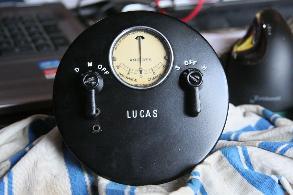
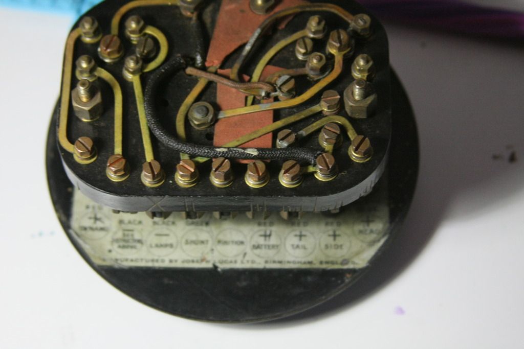
Next query - Lucas switch panel - see pics below. Its marked CS6 and CS12 on a label on the back of the facia.
For the rear view, the connectors from right to left are - Head, Side, Tail, Battery +ve, Ignition -Magneto for killing, S-shunt on Dynamo, -Ve for lamps, Battery -Ve, Dynamo.
The Battery +ve has lost its grub screw, and while it has no visible connections, a meter shows 7 Ohms to the Head connector, 28 Ohm to Side and Tail, and 0 Ohm to the cut-out frame, all others open circuit.
The Off/S/H switch makes sense, no problem. The Off on the other switch grounds the Magneto - switch off. Whats the M for - nothing connected?
The D position seems to connect Dynamo +ve to the shunt connector. On the back of this switch there is a non original wire permanently setting the switch in the D position.
There is some sort of cut out relay inside, as shown on diagram.
I have only one wire visible coming out of the dynamo - something missing ?
Does this all make sense? Why would the Off/M/D switch be hard wired to D mode - does this connect dynamo output to the battery?
I also have a Lucas ER1145 part that came with the car, but not sure its relevant - one small cap labelled Fuse cover, with 4 wire connectors, and a fuse in it; a larger cover has a cut out under it. The rear of the base is marked 'Model GF Type ??'.
Anybody able to clarify any of this please?
Thanks
jp |
|
| Back to top |
|
|
47Jag
Joined: 26 Jun 2008
Posts: 1480
Location: Bothwell, Scotland
|
| Posted: Fri Jun 24, 2016 2:44 pm Post subject: |
|
|
JP,
The Dynamo on your car is a 3 brush type. The means that there is no external regulation as such. The output of the Dynamo is done by moving the 3rd brush. On cheaper cars the battery could suffer from overcharging. If the 3rd brush is set to provide enough current to power the headlamps etc. at night then during the day it will still try and pump out the higher current whether the battery is fully charged or not. On your car which would be at the high end of the price range you get a modicum of control over the Dynamo output via a switchable resister. I hope this helps.
Art |
|
| Back to top |
|
|
goneps
Joined: 18 Jun 2013
Posts: 601
Location: Auckland, New Zealand
|
| Posted: Fri Jun 24, 2016 10:51 pm Post subject: |
|
|
While I can't claim any specific knowledge of electrics of this vintage, logic would suggest the following:
No surprise that nothing is wired to the M position. As you've stated, OFF earths the magneto to stop the engine, and that's the only control a magneto needs. If not earthed it will fire when turned—Q.E.D.
D activates the dynamo, but for normal daytime running in the days before brake lights, indicators, coil ignition, and all the other paraphernalia we now take for granted, constantly charging the battery when nothing is being drawn from it is pointless and will result in overcharging, as Art has suggested—especially if the engine is hand started, as was still common practice at this time.
In the 'thirties, when electric starting and coil ignition had become the norm and constant charging therefore became necessary, Lucas 3-brush systems incorporated a means of manual regulation by providing Summer half-charge and Winter full-charge options via the PLC switch on the dashboard. The switch also controls the lighting and automatically adjusts the charge rate when lights are in use. In your case it's entirely down to the driver to decide what's necessary to keep the battery charged but not overcharged.
Richard |
|
| Back to top |
|
|
jp928
Joined: 07 Jun 2016
Posts: 249
Location: Australia
|
| Posted: Sun Jun 26, 2016 6:01 am Post subject: |
|
|
So a single lead on the dynamo is normal for the period? Will anything come to harm if I run the motor without the dyno connected to anything?
The engine rebuild invoice (includes dyno, starter and maggy) says dyno output will need adjusting on first startup....how is this done ? Is a PLC switch something that could be added without harming the look of things?
As I mentioned above I have the Lucas ER1145 part that has some sort of cutout in it - could this be doing some output control?
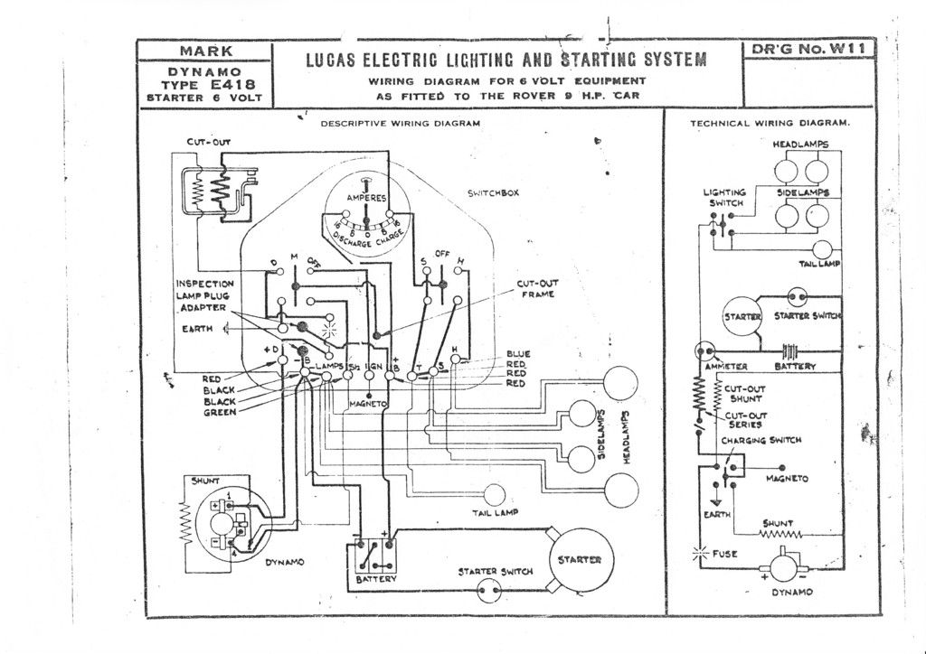
Dont forget that this car does NOT have chassis earth according to another owner. If the dyno lead I have goes to +ve, where does its -ve connection come from? Its shown on the wiring diagram I have, which looks like its not for a 3 brush dyno.
Thanks
jp
 |
|
| Back to top |
|
|
peter scott

Joined: 18 Dec 2007
Posts: 7119
Location: Edinburgh
|
| Posted: Sun Jun 26, 2016 9:17 am Post subject: |
|
|
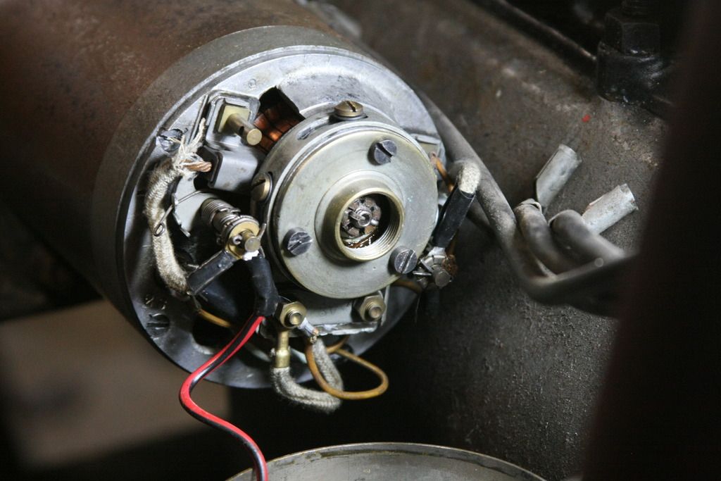
It looks like a three brush dynamo and slackening the screws on the slotted holes of the circular thing in your photo will allow you to rotate the position of the third brush. This will adjust the output current. The third brush is contained in the thing with the two brass nuts at the bottom of the circular thing and that is what you will grab to rotate it.
The negative connection on the dynamo is at the brush 180 degrees away from the positive brush. i.e. The other terminal with a small split pin retaining the connections.
Peter
_________________
http://www.nostalgiatech.co.uk
1939 SS Jaguar 2 1/2 litre saloon |
|
| Back to top |
|
|
jp928
Joined: 07 Jun 2016
Posts: 249
Location: Australia
|
| Posted: Sun Jun 26, 2016 9:59 am Post subject: |
|
|
Terrific, thanks, thats a big help! The contact of the red/black lead on the post doesnt seem all that good - is this normal practice for the period? Is there another screw hiding out of sight under the shaft? Still havent worked out the dyno can be removed from the chain drive without something major going wrong.
thanks
jp |
|
| Back to top |
|
|
peter scott
Joined: 18 Dec 2007
Posts: 7119
Location: Edinburgh
|
| Posted: Sun Jun 26, 2016 11:10 am Post subject: |
|
|
Hi jp,
I'm not familiar with the terminal arrangement on your dynamo but I guess it relies on spring pressure to maintain a good electrical contact. I did wonder whether the cables were intended to connect to brass posts like the one I see on the left hand brush housing but I can't tell from your photo whether there is a similar brass post on the negative brush housing.
I can't help any more than others have said about retaining the chain sprocket. All I would say is treat with caution and if all else fails you may have a rather bigger dismantling and reassembly job on your hands. Personally I would paint what you can see and leave it in situ.
Peter
_________________
http://www.nostalgiatech.co.uk
1939 SS Jaguar 2 1/2 litre saloon |
|
| Back to top |
|
|
47Jag
Joined: 26 Jun 2008
Posts: 1480
Location: Bothwell, Scotland
|
| Posted: Sun Jun 26, 2016 12:13 pm Post subject: |
|
|
| Quote: | | So a single lead on the dynamo is normal for the period |
I would say not. The wiring diagram shows that there should be three external terminals on the Dynamo. Is there any sign of the shunt resister that adjusts the output inside the Dynamo?
Art |
|
| Back to top |
|
|
jp928
Joined: 07 Jun 2016
Posts: 249
Location: Australia
|
| Posted: Sun Jun 26, 2016 1:36 pm Post subject: |
|
|
A shunt resistor is not visible, but its hard to see much more than the pic without removing the unit. I am inclined to leave it in place and clean up the accessible surface unless I have to go further. The plate between the two brass nuts looks like it is stamped with "6V" so maybe there is something mounted under there. I will try to get a look from below - might need to borrow a mirror from somewhere!
I have a complete spare engine & g'box with same dynamo, but without the access hole in front of the dynamo, so I might explore how that dynamo comes out, if it will.
thanks
jp |
|
| Back to top |
|
|
peter scott
Joined: 18 Dec 2007
Posts: 7119
Location: Edinburgh
|
| Posted: Sun Jun 26, 2016 5:06 pm Post subject: |
|
|
Although it is drawn looking like a resistor I think it's actually a winding within the dynamo. You'll see the same symbology used for the cut-out coils.
Peter
_________________
http://www.nostalgiatech.co.uk
1939 SS Jaguar 2 1/2 litre saloon |
|
| Back to top |
|
|
jp928
Joined: 07 Jun 2016
Posts: 249
Location: Australia
|
| Posted: Mon Jun 27, 2016 2:10 am Post subject: |
|
|
Bit more info from using a mirror.
There is brown wire from the -ve brush that goes to body of unit, and also to a post marked "2S".
A brown wire goes from the 3rd brush terminal to the interior of the unit/
A grey wire from the 2S post to the interior.
The dyno on the spare engine also only has one wire coming out of the cover - the engine is marked "25?", and has an earlier engine no than the car, which is listed as 1926.
The fact that the -ve brush lead goes to the body would indicate its using an earth return in the charging circuit at least - correct ?
The last screw holding the 3rd brush adjuster will be a bit of a bugger to get at. Might need a more robust ammeter than the DVM currently in hand to test this area.
thanks
jp |
|
| Back to top |
|
|
|


