
Classic cars forum & vehicle restoration.
|
|
| Author |
Message |
peter scott

Joined: 18 Dec 2007
Posts: 7119
Location: Edinburgh
|
 Posted: Mon Jun 27, 2016 8:41 am Post subject: Posted: Mon Jun 27, 2016 8:41 am Post subject: |
 |
|
| jp928 wrote: |
The fact that the -ve brush lead goes to the body would indicate its using an earth return in the charging circuit at least - correct ?
jp |
Yes, that's what your wiring diagram shows.
Peter
_________________
http://www.nostalgiatech.co.uk
1939 SS Jaguar 2 1/2 litre saloon |
|
| Back to top |
|
 |
Tony Press
Joined: 07 Mar 2011
Posts: 10
|
| Posted: Mon Jun 27, 2016 11:14 pm Post subject: |
|
|
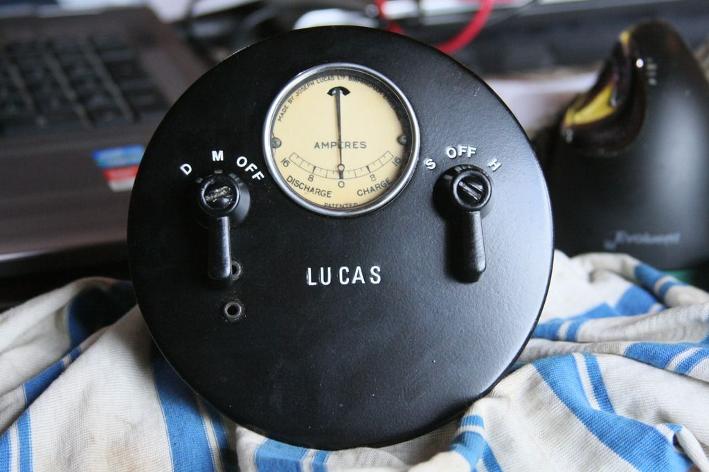
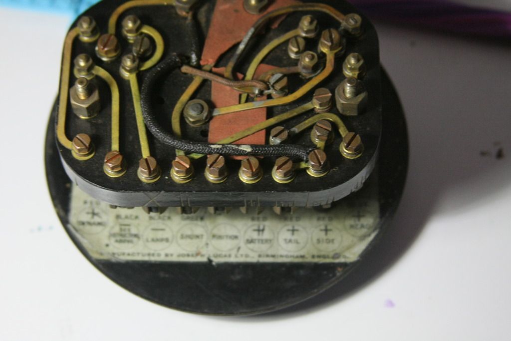
| jp928 wrote: | Next query - Lucas switch panel - see pics below. Its marked CS6 and CS12 on a label on the back of the facia.
For the rear view, the connectors from right to left are - Head, Side, Tail, Battery +ve, Ignition -Magneto for killing, S-shunt on Dynamo, -Ve for lamps, Battery -Ve, Dynamo.
The Battery +ve has lost its grub screw, and while it has no visible connections, a meter shows 7 Ohms to the Head connector, 28 Ohm to Side and Tail, and 0 Ohm to the cut-out frame, all others open circuit.
The Off/S/H switch makes sense, no problem. The Off on the other switch grounds the Magneto - switch off. Whats the M for - nothing connected?
The D position seems to connect Dynamo +ve to the shunt connector. On the back of this switch there is a non original wire permanently setting the switch in the D position.
There is some sort of cut out relay inside, as shown on diagram.
I have only one wire visible coming out of the dynamo - something missing ?
Does this all make sense? Why would the Off/M/D switch be hard wired to D mode - does this connect dynamo output to the battery?
I also have a Lucas ER1145 part that came with the car, but not sure its relevant - one small cap labelled Fuse cover, with 4 wire connectors, and a fuse in it; a larger cover has a cut out under it. The rear of the base is marked 'Model GF Type ??'.
Anybody able to clarify any of this please?
Thanks
jp |
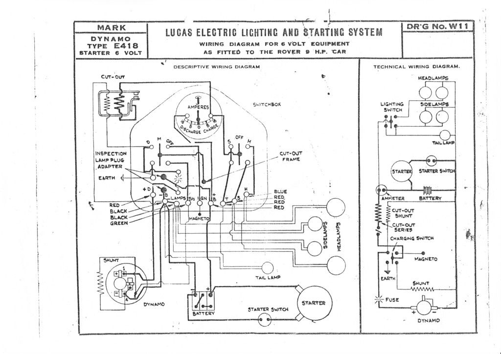
I am having difficulty in understanding the wiring diagram- (not unusual) but the system is shown as earth return with wiring to earth for most connections.
The cutout seems to not be earthed to allow the dynamo to feed the system, but I cannot understand the dynamo third brush connection which seems to be shown as connected to earth ?
Is the 'shunt' the dynamo field winding - the wiring suggests so (it doesn't seem to have summer half charge) - I would have thought this went to the dynamo output when 'D' is switched in.
Just my musings after much looking at the diagram.
Confused of Malvern Australia. |
|
| Back to top |
|
|
peter scott
Joined: 18 Dec 2007
Posts: 7119
Location: Edinburgh
|
| Posted: Tue Jun 28, 2016 12:00 pm Post subject: |
|
|
I confess that I don't understand the earthed third brush either. The cut-out is quite normal and has its shunt coil across the dynamo output and a series coil just to add to the pull current and prevent the contacts from chattering at lower voltages.
I suspect that the shunt on the dynamo is the field coil although diagramitically it is shown external to the casing. See if you can trace the connections to it and you might discover what and where it is. With the switch in the M position it should be possible to measure the resistance of the shunt. There might be more than one field winding and this shunt might be adding or opposing the magnetism as selected by the D or M switch positions.
Operating it in the car should tell you what's what.
HTH
Peter
_________________
http://www.nostalgiatech.co.uk
1939 SS Jaguar 2 1/2 litre saloon |
|
| Back to top |
|
|
jp928
Joined: 07 Jun 2016
Posts: 249
Location: Australia
|
| Posted: Wed Jun 29, 2016 5:55 am Post subject: |
|
|
Back to the starter - on further inspection there are 4 screws holding the mounting face onto the body. On removal it was very easy to rotate the plate 90d, without any electrics being involved, and the connections are now safe and in the same position as the other examples.
Another win, only a few 100 more to go...
thanks
jp |
|
| Back to top |
|
|
jp928
Joined: 07 Jun 2016
Posts: 249
Location: Australia
|
| Posted: Wed Jul 06, 2016 4:00 am Post subject: |
|
|
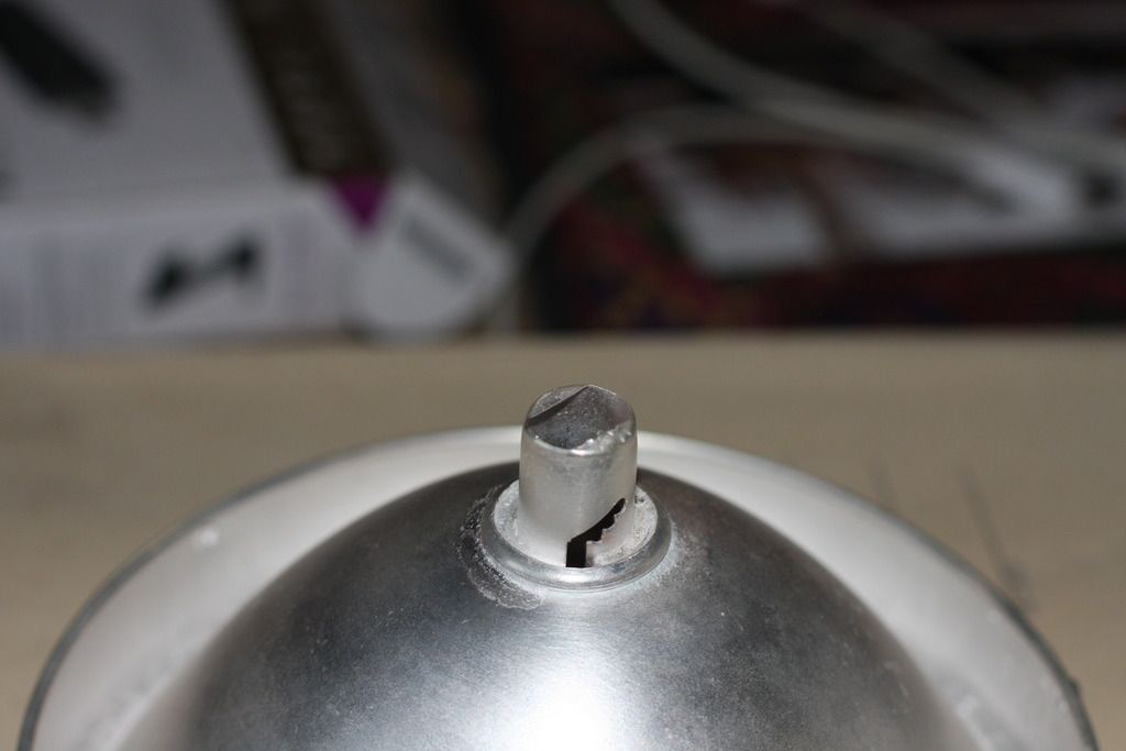
Next query - the headlight bulb holder seems incomplete - am I missing some sort of spring loaded electrical contact here. The unit is a Lucas R40M.
Whats the std wattage one would use for a 6V bulb here ?
tks
jp
 |
|
| Back to top |
|
|
goneps
Joined: 18 Jun 2013
Posts: 601
Location: Auckland, New Zealand
|
| Posted: Wed Jul 06, 2016 4:27 am Post subject: |
|
|
Can't help with the bulb holder I'm afraid, but I'd guess the wattage would be 24/24W—certainly no more. That's 8 amps just for the headlamps, and the dynamo may only have a maximum output around 10-12A.
In my experience the majority of those who complain bitterly about 6V lighting are the ones who put in bulbs of higher wattage than the dynamo can support.
Richard |
|
| Back to top |
|
|
47Jag
Joined: 26 Jun 2008
Posts: 1480
Location: Bothwell, Scotland
|
| Posted: Wed Jul 06, 2016 4:31 pm Post subject: |
|
|
PJ,
I think the part you are looking for is a plastic contact holder that were used in a lot of Lucas lamps. They come in single and double contact and have the two flat sides to keep them in position on the reflector. I think the get centre punched in the side paso that they don't fall out. I found these which may be use as substitute. Item 153 or 153s.
https://www.completeautomobilist.com/search?query=Bulb+holder
Art |
|
| Back to top |
|
|
MVPeters

Joined: 28 Aug 2008
Posts: 822
Location: Northern MA, USA
|
| Posted: Wed Jul 06, 2016 8:02 pm Post subject: |
|
|
That's a bulb holder for a single contact bayonet bulb, a BA15, BA15S or SBC.
Note there are 3 detents for the bayonet - they are to adjust the focus.
If you can find any yellow-lens rear light unit off a Mini or MGB or hundreds of others, you can pull out the spring-loaded bit from the front & insert it in your reflector. Even the 21W bulb will work, though it may not be optimum.
The correct bulb would be a bit larger & more global in shape.
(Edited to add - 12V bulbs will be dim! but you get the idea).
_________________
Mike - MVPeters at comcast.net
2002 MINI Cooper 'S' |
|
| Back to top |
|
|
jp928
Joined: 07 Jun 2016
Posts: 249
Location: Australia
|
| Posted: Wed Jul 06, 2016 11:30 pm Post subject: |
|
|
Excellent, thanks guys! Will look for such an item down here, or order from UK next time I need something else from there. Another problem solved!
jp |
|
| Back to top |
|
|
jp928
Joined: 07 Jun 2016
Posts: 249
Location: Australia
|
| Posted: Thu Aug 11, 2016 2:48 am Post subject: |
|
|
As a final note on the starter - having got some wiring in place and a battery ready. I wired an isolation switch on the main +12V feed, with live side to the new loom, and heavy lead to the starter. Starter switch is in the negative heavy lead as in the wiring diagram. So I thought before I chance any smoke escaping I would check some stuff - there was full battery volts across the isolator - that cant be right? The wiring diverges a bit from the diagram because the internally grounded 3rd brush requires that the dynamo body be earthed, which means the car is now neg earth. After a bit of chasing I found the neg pole of the starter was shorted to the starter body. Starter motor out again. There was a fibre washer evident INSIDE the body on the neg pole bolt isolating the internal connections....but not on the outside. When I pulled the retaining nut and washers off, there was a steel washer at the bottom. Problem found. Had a nice big fibre washer hand, enlarge the hole a bit and reassemble. That works much better now, and it cranks over as it should. Whoever overhauled the starter made an assumption , that might be safe on modern starters, but wrong in this case.
jp |
|
| Back to top |
|
|
|
|
You cannot post new topics in this forum
You cannot reply to topics in this forum
You cannot edit your posts in this forum
You cannot delete your posts in this forum
You cannot vote in polls in this forum
|
php BB powered © php BB Grp.
|


