|
|
| Author |
Message |
robo0121
Joined: 11 Nov 2013
Posts: 49
Location: Birmingham West Midlands
|
 Posted: Mon Sep 05, 2016 9:24 pm Post subject: standard 10 Posted: Mon Sep 05, 2016 9:24 pm Post subject: standard 10 |
 |
|
Hi all cant seem to get the indicators working on my standard 10..i know its not rocket science as there is only 4 wires replaced the flasher unit..nothing.am I missing summat...I know someone out there can help me..so please all suggestions welcome..thanks  |
|
| Back to top |
|
 |
Peter_L
Joined: 10 Apr 2008
Posts: 2680
Location: New Brunswick. Canada.
|
| Posted: Mon Sep 05, 2016 9:49 pm Post subject: |
|
|
I have never owned a Standard 10, but have had quite a few vehicles and worked on many more, so question.
Where in the scheme of things is the location where you have 4 wires ? |
|
| Back to top |
|
|
robo0121
Joined: 11 Nov 2013
Posts: 49
Location: Birmingham West Midlands
|
| Posted: Mon Sep 05, 2016 10:19 pm Post subject: standard 10 |
|
|
| the 4 wires are coming from the indicator arm |
|
| Back to top |
|
|
Peter_L
Joined: 10 Apr 2008
Posts: 2680
Location: New Brunswick. Canada.
|
| Posted: Mon Sep 05, 2016 10:49 pm Post subject: |
|
|
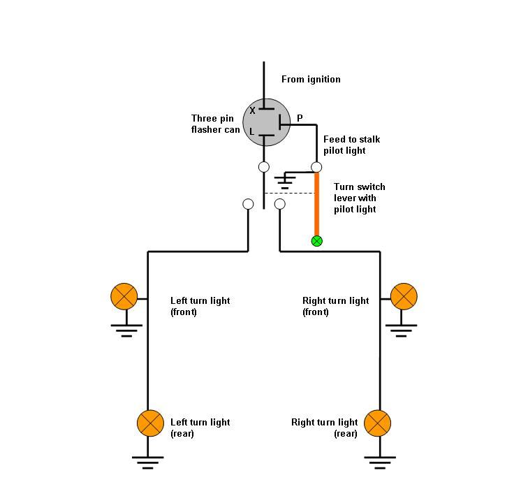
If the turn signal warning light is on the end of the indicator switch the 4 wires may be as per drawing. A simple multimeter will prove what bits of the circuit are working at the switch.
 |
|
| Back to top |
|
|
robo0121
Joined: 11 Nov 2013
Posts: 49
Location: Birmingham West Midlands
|
| Posted: Mon Sep 05, 2016 10:56 pm Post subject: standard 10 |
|
|
| thanks Peter |
|
| Back to top |
|
|
robo0121
Joined: 11 Nov 2013
Posts: 49
Location: Birmingham West Midlands
|
| Posted: Sat Sep 10, 2016 10:09 am Post subject: standard 10 |
|
|
| Still no joy on indicators .any other tips out there..getting really frustrating now it should be so easy I know..but it aint.so any suggestions will be welcomed..thanks |
|
| Back to top |
|
|
Peter_L
Joined: 10 Apr 2008
Posts: 2680
Location: New Brunswick. Canada.
|
| Posted: Sat Sep 10, 2016 12:46 pm Post subject: Re: standard 10 |
|
|
| robo0121 wrote: | | Still no joy on indicators .any other tips out there..getting really frustrating now it should be so easy I know..but it aint.so any suggestions will be welcomed..thanks |
Do you have a multimeter ? Also find a small wattage 12v bulb and attach two fairly long electrical wires. If at all possible attach a crocodile clip to the end of them.
With these two items, electrical problems can go from guessing to logic.
I have known those who waste a lot of time and get really frustrated. by swapping bulbs, switches, and other bits in a haphazard attempt to find the fault. Logic and a notebook makes the task easier. |
|
| Back to top |
|
|
Rick
Site Admin

Joined: 27 Apr 2005
Posts: 22449
Location: UK
|
|
| Back to top |
|
|
Peter_L
Joined: 10 Apr 2008
Posts: 2680
Location: New Brunswick. Canada.
|
| Posted: Sat Sep 10, 2016 6:53 pm Post subject: |
|
|
| Rick wrote: | I'd be testing for power at each (indicator) bulb holder, with the switch in the relevant "on" position, using a test lamp or better a multimeter, then working my way back up the line to the flasher relay, and then back to the switch, to see if there's at least power circulating as it should.
I assume all the connections have been checked and cleaned up as necessary?
RJ |
Hi Rick and Robo. Not wishing to be a "yawn" about this. But I would begin the troubleshooting at the known source of the circuitry, which on many such circuits may be an ignition switch fed fuse. From there it would go to the flasher unit. Bridge the flasher unit an operate the switch. If the left and right lights come on, then the flasher is suspect. If not, test circuit at switch common and then on each output. |
|
| Back to top |
|
|
|


