|
|
| Author |
Message |
Vulgalour
Joined: 08 May 2018
Posts: 475
Location: Kent
|
 Posted: Sun May 08, 2022 8:34 pm Post subject: Wiring Nightmare Posted: Sun May 08, 2022 8:34 pm Post subject: Wiring Nightmare |
 |
|
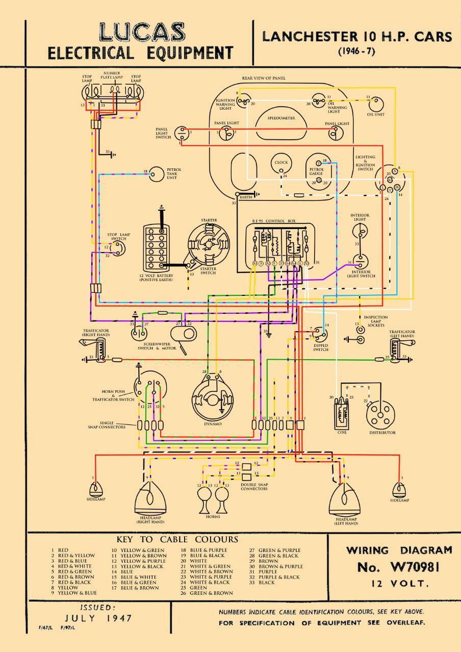
I have spent today methodically making sure the Lanchester doesn't work anymore. I had a problem where the putting the headlights on turned all the rear lights off. Suggestions were that this was either a mis-wired ignition switch, dirty ignition switch contacts, or both. I checked the wiring against the diagram below, the photos of the car as it came to us, and the two Lanchester wiring diagrams and believe it's correct.

Then I tried to work out which of the references for the wiring I was working from was closest to correct. It was so frustrating I made a crib sheet, like so.

This made things about as clear as mud. It's worth noting on the 46-7 diagram the reference letters/numbers for the voltage regulator are different to the other references I've got, so could well be incorrect. Spent most of the day trying to find some commonality and common sense with what was on the car and gradually made sure the lights all stopped working completely. No idea what I've done to be honest, the battery isn't showing as flat so I imagine I must have done something wrong, or the ignition switch has completely failed or something, I don't know.
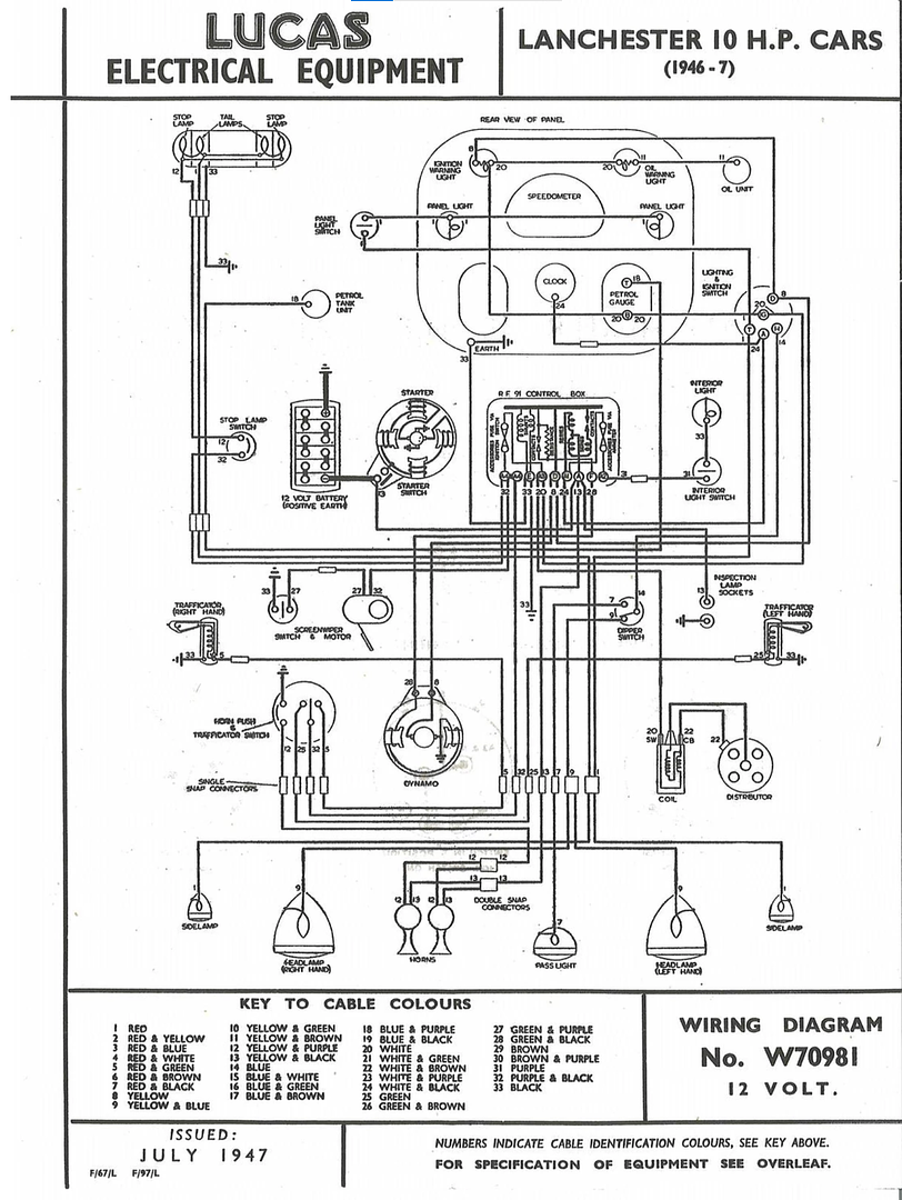
I've tried to go through a system at a time to get things to work, going with sidelights, headlights, and main beam. In trying to fix the headlight/sidelight issue I've only succeeded in making everything inoperative and I've no idea how. Below is the updated wiring diagram to show where I'm at with things. I must have wired something up stupid, or I've burned out a component or something. I just want it to work.
I've spent so long on this job now I'm about ready to throw the towel in. I must be missing something obvious, or there's a component that's failed, or something. I don't know and it's driving me spare. This should be a simple job and it's proven to be anything but.
If you can see what I've done wrong please let me know. I really don't know what to do on this any more. |
|
| Back to top |
|
 |
Vulgalour
Joined: 08 May 2018
Posts: 475
Location: Kent
|
| Posted: Mon May 09, 2022 10:48 am Post subject: |
|
|
Further to the above I removed the ignition switch to test for continuity and functionality. I'm getting reliable results, whether they're the correct results I don't know.

On both of the wiring diagrams I have for this car, nothing is connected to socket L on the switch. I don't know at this point if that means the switch is wrong or the diagrams are wrong. Both diagrams did agree on the wiring layout and that correlates with the wiring the car came to us with, so that's how it is.
I had the switch wired as below.

Colours for the above are:
red - rear sidelights and number plate light
red - front sidelights
yellow (x2) - A at switch to A1 at voltage regulator
white (x2) - A3 a switch to A3 at voltage regulator
white/black - Clock/dashboard (I don't know where this is supposed to connect)
blue - headlamp dip switch
I'm still stumped on this one. |
|
| Back to top |
|
|
peter scott

Joined: 18 Dec 2007
Posts: 7124
Location: Edinburgh
|
| Posted: Mon May 09, 2022 8:19 pm Post subject: |
|
|
To establish where the problem lies use your meter to check the voltage on the T terminal of your lighting switch relative to the E terminal on the control box, with and without the headlamps switched on.
HTH
Peter
_________________
http://www.nostalgiatech.co.uk
1939 SS Jaguar 2 1/2 litre saloon |
|
| Back to top |
|
|
bjacko
Joined: 28 Oct 2013
Posts: 364
Location: Melbourne Australia
|
| Posted: Tue May 10, 2022 8:19 am Post subject: Lanchester Wiring |
|
|
| Looks like you should have the lights connected to L not T which is the feed from the D on the RF95 regulator as per your first diagram. |
|
| Back to top |
|
|
Ray White

Joined: 02 Dec 2014
Posts: 6342
Location: Derby
|
| Posted: Tue May 10, 2022 9:47 am Post subject: |
|
|
| I thought T was for tail lights and H for headlights. That is what I have on mine. |
|
| Back to top |
|
|
ukdave2002
Joined: 23 Nov 2007
Posts: 4117
Location: South Cheshire
|
| Posted: Tue May 10, 2022 4:18 pm Post subject: |
|
|
I'm struggling to understand the issue here, the first Lucas diagram nails it, why deviate from that ?
Dave |
|
| Back to top |
|
|
Ray White
Joined: 02 Dec 2014
Posts: 6342
Location: Derby
|
| Posted: Tue May 10, 2022 5:10 pm Post subject: |
|
|
| ukdave2002 wrote: | I'm struggling to understand the issue here, the first Lucas diagram nails it, why deviate from that ?
Dave |
This is different to mine. Here it seems L is for side lights; it is left unused on mine. |
|
| Back to top |
|
|
ukdave2002
Joined: 23 Nov 2007
Posts: 4117
Location: South Cheshire
|
| Posted: Wed May 11, 2022 7:25 am Post subject: |
|
|
| Ray White wrote: | | ukdave2002 wrote: | I'm struggling to understand the issue here, the first Lucas diagram nails it, why deviate from that ?
Dave |
This is different to mine. Here it seems L is for side lights; it is left unused on mine. |
Sorry, I take my previous comment back back  looking closer at that Lucas diagram its been doctored, by I assume who ever put the coloured wiring overlay on the original Lucas drawing, a few obvious things are wrong: looking closer at that Lucas diagram its been doctored, by I assume who ever put the coloured wiring overlay on the original Lucas drawing, a few obvious things are wrong:
On the Lucas diagram it shows the dynamo output going to "A1" on the RF95, it should go to "D"
The internals of the RF95 are also incorrect, it shows a fuse between A1 and F, this is incorrect the fuse is in fact between A1 & A2.
Unfortunately if the output of the dynamo has been wired to A1 it will have put the entire dynamo output through the RF95 series windings and depending how this affected the contacts, if its gone back to the dynamo Field (F) without any regulation the voltage output of the dynamo will have just kept rising to around 40v potentially burning out bulbs and Control box windings and or contacts.
Also is the car fitted with an RF95 control box, vehicles of that era could also have an RF91 control box, they are interchangeable but confusingly not labelled in exactly the same way. The graphic for the control box looks like the RF91, however its labelled as RF95, again I think is a badly doctored diagram.
Terminal L (Low) on the PLC6 switch is very seldom used, being originally incorporated for three lamp lighting sets where head/side lamps on the wings carried bulbs with dim and bright filaments, the former acting as side lamps. Terminal L is alive in side position only and cannot be used for normal side lamp feed as it is dead in Head position. This terminal is used on motor cycle sets where it feeds the pilot bulb in the headlamp. Another application is on cars having a separate headlamp switch, wired from terminal L, while a pass light is wired from terminal H. In this case, position of normal "Side" becomes Sides, Rear and Headlamp, while position "Head" becomes Sides, Rear and Pass light.
Dave |
|
| Back to top |
|
|
peter scott
Joined: 18 Dec 2007
Posts: 7124
Location: Edinburgh
|
|
| Back to top |
|
|
MikeEdwards
Joined: 25 May 2011
Posts: 2479
Location: South Cheshire
|
| Posted: Wed May 11, 2022 9:19 am Post subject: |
|
|
| ukdave2002 wrote: | | looking closer at that Lucas diagram its been doctored, by I assume who ever put the coloured wiring overlay on the original Lucas drawing |
Slightly off-topic, but I'd love to know of a free drawing tool for doing that sort of stuff, as I've been trying to do a decent wiring diagram for my car. I can draw coloured lines over a scan without any trouble, but making the colour-with-trace wires is extremely time-consuming.
_________________
1976 Vauxhall HP Firenza, 1976 Vauxhall Sportshatch (x2), 1986 Audi coupe quattro, 2000 Audi TT |
|
| Back to top |
|
|
Ray White
Joined: 02 Dec 2014
Posts: 6342
Location: Derby
|
| Posted: Wed May 11, 2022 9:30 am Post subject: |
|
|
I have searched all my old books but the Lanchester 10 wiring diagram seems conspicuous by it's absence.
Sorry I can't help. |
|
| Back to top |
|
|
Rick
Site Admin

Joined: 27 Apr 2005
Posts: 22458
Location: UK
|
|
| Back to top |
|
|
ukdave2002
Joined: 23 Nov 2007
Posts: 4117
Location: South Cheshire
|
| Posted: Wed May 11, 2022 9:39 am Post subject: |
|
|
 |
|
| Back to top |
|
|
Ray White
Joined: 02 Dec 2014
Posts: 6342
Location: Derby
|
| Posted: Wed May 11, 2022 9:39 am Post subject: |
|
|
There is one here on line (it won't let me lift it).
http://ld10.awardspace.co.uk/articles/trader138.pdf
It shows an RF 91 voltage regulator.
The side lights are taken from T on the switch.
(Dave beat me to it!) |
|
| Back to top |
|
|
ukdave2002
Joined: 23 Nov 2007
Posts: 4117
Location: South Cheshire
|
| Posted: Wed May 11, 2022 9:55 am Post subject: |
|
|
| Ray White wrote: | | It shows an RF 91 voltage regulator. |
Yep, I think that's the crux of the problem, whoever modified the original Lucas diagram, has tried to insert the RF95 terminal layout, onto the RF91 in the drawing, and made a pigs ear of the job! No wonder Vulgalour is confused.
Dave |
|
| Back to top |
|
|
|


