|
|
| Author |
Message |
Ray White

Joined: 02 Dec 2014
Posts: 6342
Location: Derby
|
 Posted: Thu Jan 28, 2021 12:47 am Post subject: Posted: Thu Jan 28, 2021 12:47 am Post subject: |
 |
|
I will have to study it tomorrow. All this relay stuff has given me a headache!  |
|
| Back to top |
|
 |
Peter_L
Joined: 10 Apr 2008
Posts: 2680
Location: New Brunswick. Canada.
|
| Posted: Thu Jan 28, 2021 7:38 am Post subject: |
|
|

Basic wiring diagram for relay/s
The relay coil/actuator only takes very small current. 85-86
The contacts within the relay 30 - 87 (Normally open) take the higher current required by the load, such as a Horn or Lights.
The fuse protects the wiring and relay contacts from damage in the event of a fault/overload in either the load or its associated wiring. |
|
| Back to top |
|
|
Ray White
Joined: 02 Dec 2014
Posts: 6342
Location: Derby
|
| Posted: Thu Jan 28, 2021 1:52 pm Post subject: |
|
|
The diagram shows the small current being taken to the relay AFTER the switch. MUST the layout ALWAYS be like this?
I have the current going from the A1 fused terminal to the relay first then onto the switched load. |
|
| Back to top |
|
|
badhuis

Joined: 20 Aug 2008
Posts: 1392
Location: Netherlands
|
| Posted: Thu Jan 28, 2021 3:19 pm Post subject: |
|
|
| Ray White wrote: | | The diagram shows the small current being taken to the relay AFTER the switch. MUST the layout ALWAYS be like this? |
Yes, that is the main reason for having a relay. The switch when switched on makes the relay work: full current to the load. There is only a small current going through the switch now which means the switch will never burn out.
_________________
a car stops being fun when it becomes an investment |
|
| Back to top |
|
|
Ray White
Joined: 02 Dec 2014
Posts: 6342
Location: Derby
|
| Posted: Thu Jan 28, 2021 4:06 pm Post subject: |
|
|
| badhuis wrote: | | Ray White wrote: | | The diagram shows the small current being taken to the relay AFTER the switch. MUST the layout ALWAYS be like this? |
Yes, that is the main reason for having a relay. The switch when switched on makes the relay work: full current to the load. There is only a small current going through the switch now which means the switch will never burn out. |
Thank you Badhuis. I should have realised that before. |
|
| Back to top |
|
|
Ray White
Joined: 02 Dec 2014
Posts: 6342
Location: Derby
|
| Posted: Thu Jan 28, 2021 5:46 pm Post subject: |
|
|
| As heavy current will only be pulled through the wires supplying the headlamps, will the two relays that cover the main and dip beam switch automatically protect the main switch? |
|
| Back to top |
|
|
Ray White
Joined: 02 Dec 2014
Posts: 6342
Location: Derby
|
| Posted: Sun Jan 31, 2021 5:38 pm Post subject: |
|
|
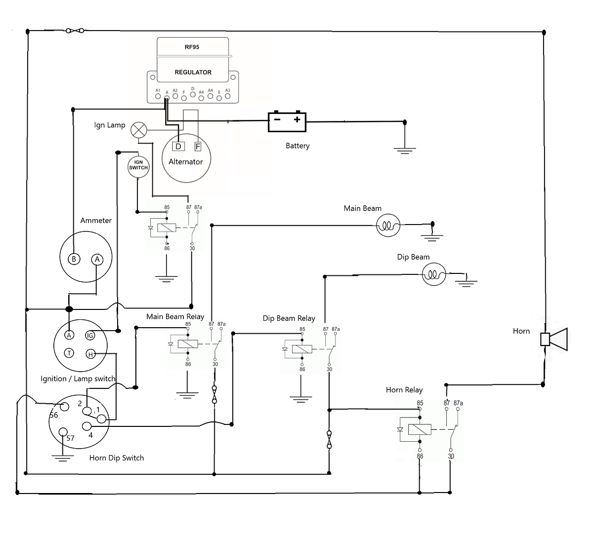
Here is another attempt at a diagram which aims to show how relays might fit into the re wire of my MG TC.
Please feel free to pick me up on errors etc.
 |
|
| Back to top |
|
|
DM

Joined: 21 Dec 2008
Posts: 212
Location: North Cornwall
|
| Posted: Sun Jan 31, 2021 10:52 pm Post subject: |
|
|
Link across A1 and A2 on the regulator bypasses the accessory fuse.
Alternator output wants to go to the A terminal on the regulator, alternator wired as per your drawing means the ammeter will not read correctly.
Will only read the current drawn by the car without taking into account the charge current from the alternator. |
|
| Back to top |
|
|
Ray White
Joined: 02 Dec 2014
Posts: 6342
Location: Derby
|
| Posted: Mon Feb 01, 2021 1:11 am Post subject: |
|
|
The instructions that come with the dynamater show it not connected to the regulator at all.?/Users/raywhite-newair/Desktop/http-::www.accuspark.co.uk:InstructionsPDF:Dynamator%20Positive%20Earth%20Instructions.pdf 2.webloc
Sorry, I can't seem to paste it like you did...
BTW I get the point about the A1 A2 fuse link error. |
|
| Back to top |
|
|
DM
Joined: 21 Dec 2008
Posts: 212
Location: North Cornwall
|
| Posted: Mon Feb 01, 2021 10:30 am Post subject: |
|
|
Your diagram has the alternator feed on the wrong side of the ammeter which will mean the ammeter will never show the charge current.
As long as the alternator output is connected to the A side of the ammeter the ammeter will read correctly. |
|
| Back to top |
|
|
Ray White
Joined: 02 Dec 2014
Posts: 6342
Location: Derby
|
| Posted: Mon Feb 01, 2021 10:59 am Post subject: |
|
|
| DM wrote: | Your diagram has the alternator feed on the wrong side of the ammeter which will mean the ammeter will never show the charge current.
As long as the alternator output is connected to the A side of the ammeter the ammeter will read correctly. |
Oh YES!! Thank you for pointing that out! |
|
| Back to top |
|
|
Ray White
Joined: 02 Dec 2014
Posts: 6342
Location: Derby
|
| Posted: Mon Feb 01, 2021 12:49 pm Post subject: |
|
|
One thing that confuses me about wiring the alternator is that the fitting instructions say take a 45 amp wire from it to the battery. I then have a heavy wire in the loom which according to the original wiring diagram (for a dynamo) should be connected from the starter switch to the 'B' side of the ammeter.
It has now been explained that the alternator needs to be connected to the 'A' side. This would mean that I will have wires from the - battery terminal to BOTH sides of the ammeter ...which I don't understand.??? |
|
| Back to top |
|
|
ukdave2002
Joined: 23 Nov 2007
Posts: 4117
Location: South Cheshire
|
| Posted: Mon Feb 01, 2021 5:23 pm Post subject: |
|
|
Hi Ray as promised:
Whilst the RF 95 has fuses its less complicated no to use them, and you avoid have in circuits with 2 fuses.
Dave |
|
| Back to top |
|
|
Peter_L
Joined: 10 Apr 2008
Posts: 2680
Location: New Brunswick. Canada.
|
| Posted: Mon Feb 01, 2021 5:47 pm Post subject: |
|
|
Excellent drawing Dave.  |
|
| Back to top |
|
|
Ray White
Joined: 02 Dec 2014
Posts: 6342
Location: Derby
|
| Posted: Mon Feb 01, 2021 5:50 pm Post subject: |
|
|
Nice drawing, Dave. Thank you.
It looks like the small wire from the alternator eventually goes to the ammeter at A.
I will get it right eventually. |
|
| Back to top |
|
|
|


