|
|
| Author |
Message |
Ray White

Joined: 02 Dec 2014
Posts: 6316
Location: Derby
|
 Posted: Wed Apr 07, 2021 1:33 pm Post subject: adding a horn relay Posted: Wed Apr 07, 2021 1:33 pm Post subject: adding a horn relay |
 |
|
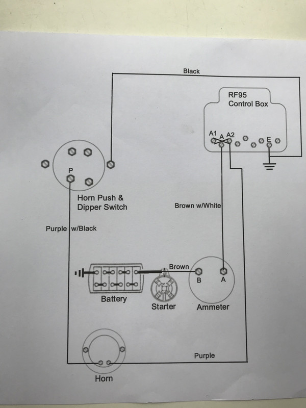
This diagram is for the TC horn as standard fit. In an attempt to preserve the ancient (and expensive to replace) push button I would like to add a relay. The horn button completes the circuit by grounding when pressed which is different from other circuits I have seen.
I would be grateful if someone could show me how a relay would work with this diagram.
(for example should I cut the purple/black wire and join the wire from 85 to the switch side and the wire from 87 to the other end to the horn.?)
I have positive earth and my relay has a diode so 86 is ground.
Thank you in advance.
 |
|
| Back to top |
|
 |
petelang
Joined: 21 May 2009
Posts: 444
Location: Nottingham
|
| Posted: Wed Apr 07, 2021 11:51 pm Post subject: |
|
|
Ray, with the greatest respect, unless you intend to be bipping your horn with annoying regularity, why go to so much trouble? It was designed that way, the switchgear is more than ample up to it and, if it ain't broke why fix it?
You are simply adding in more complications, more connections, hence more things to sort through if it ever goes wrong and knowing the quality of components today that could be a real issue.
Just drive nicely and only use the horn to REALLY make a point when it's properly necessary, unless your fitting a Train horn...
Peter
_________________
Daimler Fifteen 1934
Armstrong Siddeley 15 Long 1933
Daimler V8 250 1969 |
|
| Back to top |
|
|
ukdave2002
Joined: 23 Nov 2007
Posts: 4105
Location: South Cheshire
|
| Posted: Thu Apr 08, 2021 8:26 am Post subject: |
|
|
Ray I'd have thought you should be the site relay guru by now! 
If you want to fit one to the horn circuit, its a cut and paste of the other circuits where you have fitted relays; the original switch now switches the relay coil, making sure you have the polarity correct if a diode is fitted, the relay contacts now complete the horn circuit.
The first relays I played with were ex GPO telephone exchange relays, it was much easier to understand how they work as they are open; you can physically see the coil and the contacts.
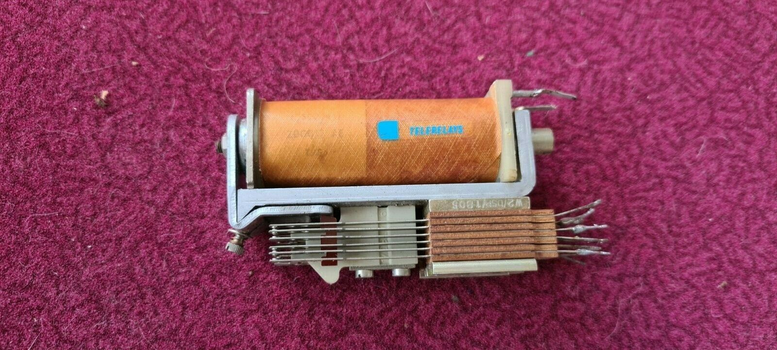
Unlike the modern vehicle ones that are in a sealed box  The relay pictured has several change over contacts. The relay pictured has several change over contacts.
Dave |
|
| Back to top |
|
|
Ray White
Joined: 02 Dec 2014
Posts: 6316
Location: Derby
|
| Posted: Thu Apr 08, 2021 8:45 am Post subject: |
|
|
I may or may not bother with a horn relay. It is more about trying to understand how to do something rather than staying ignorant and never know.
It looks to me like there is something different if pressing the horn button grounds to complete the circuit instead of allowing current through to the relay? |
|
| Back to top |
|
|
Ray White
Joined: 02 Dec 2014
Posts: 6316
Location: Derby
|
| Posted: Thu Apr 08, 2021 8:13 pm Post subject: |
|
|
| ukdave2002 wrote: | Ray I'd have thought you should be the site relay guru by now!
If you want to fit one to the horn circuit, its a cut and paste of the other circuits where you have fitted relays; the original switch now switches the relay coil, making sure you have the polarity correct if a diode is fitted, the relay contacts now complete the horn circuit.
Dave |
Dave. If I were to divide the purple and black wire and insert a relay with T85 going to the push button and T 87 connected to the other end of the same wire going to the horn ...it wouldn't work would it? It would be applying 12 v to BOTH sides of the horn, surely.? |
|
| Back to top |
|
|
ukdave2002
Joined: 23 Nov 2007
Posts: 4105
Location: South Cheshire
|
| Posted: Fri Apr 09, 2021 10:23 am Post subject: |
|
|
It wouldn't work at all as you would have the relay coil an horn wired in series.
All you need to do (and this applies to an addition of any relay) is replace the load with the relay coil (polarity sensitive if the coil has a diode across it), now you'll have a pair of contacts within the relay that will make when the horn button is pressed (30 & 87) . The horn can have a permanent earth or permanent live on one connection, the other horn connection should be attached to 87with 30 connected to earth or live; the opposite of what the permanent connection to the horn is .
Dave |
|
| Back to top |
|
|
Ray White
Joined: 02 Dec 2014
Posts: 6316
Location: Derby
|
| Posted: Fri Apr 09, 2021 1:23 pm Post subject: |
|
|
| Really all I want is to be told what colour wire goes to what number on the relay given that 86 is + ground. |
|
| Back to top |
|
|
ukdave2002
Joined: 23 Nov 2007
Posts: 4105
Location: South Cheshire
|
| Posted: Sat Apr 10, 2021 9:28 am Post subject: |
|
|
| Ray White wrote: | | Really all I want is to be told what colour wire goes to what number on the relay given that 86 is + ground. |
My previous post was attempting to teach you to fish
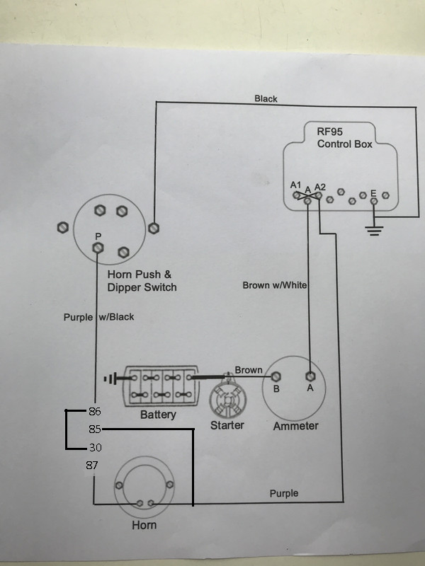
Here is the meal  when a relay has a diode the cathode it is connected to 86 of the coil, 86 should be on the +ve side of the circuit , in this scenario for a negative earth car 85 & 86 would be reversed. when a relay has a diode the cathode it is connected to 86 of the coil, 86 should be on the +ve side of the circuit , in this scenario for a negative earth car 85 & 86 would be reversed.
Last edited by ukdave2002 on Sat Apr 10, 2021 9:45 am; edited 2 times in total |
|
| Back to top |
|
|
Ray White
Joined: 02 Dec 2014
Posts: 6316
Location: Derby
|
| Posted: Sat Apr 10, 2021 9:43 am Post subject: |
|
|
Thank you so much, Dave. The theory is no doubt interesting but not what I need right now.
I have been told by someone I know that the horn would need to be earthed. Originally, the horn is insulated and grounded from a wire from the control box as shown in my original post.
I have since learned that it depends on the type of horn. It's always the same but never quite the same if you know what I mean.
This has left me confused and frustrated and doubting myself to the point of throwing in the towel with this car altogether.
What you have posted has explained nice and clear what I need to do.
Thank you again. |
|
| Back to top |
|
|
|


