|
|
| Author |
Message |
Ray White

Joined: 02 Dec 2014
Posts: 6337
Location: Derby
|
 Posted: Sat May 04, 2024 8:58 pm Post subject: ignition warning light wiring. Posted: Sat May 04, 2024 8:58 pm Post subject: ignition warning light wiring. |
 |
|
Despite much head scratching, I am not yet able to get the ignition warning lamp to illuminate.
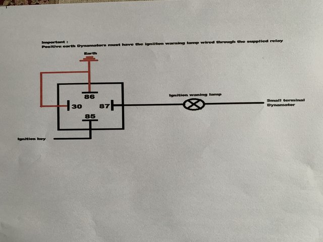
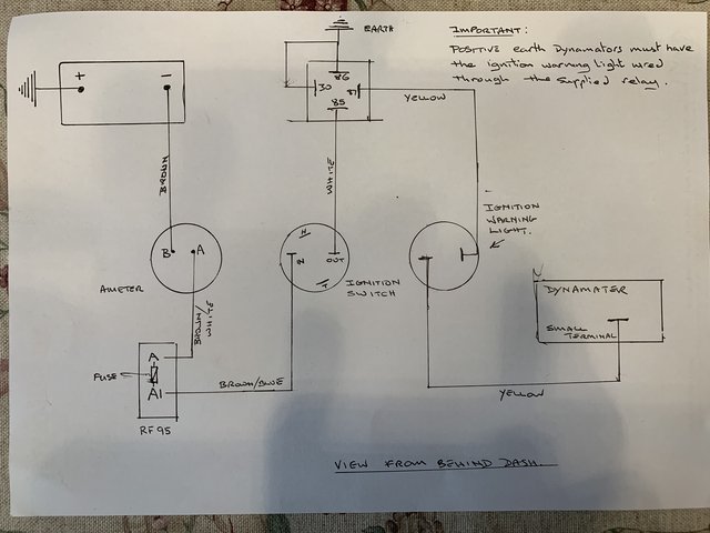
Having followed the advice from 'Stealth' with regard to fitting a relay with their Dynamator for positive earth cars, and wired in accordance with the diagrams, it is disappointing that I don't seem to be getting anywhere.
Note:
1) this relay does not have a diode
2) there is power getting to terminal 85 via the ignition switch.
3) As an alternator is now installed, the RF 95 control box has had the voltage regulation function disabled.
If my diagram needs alteration I would be glad of assistance. Please make suggestions that might help.
 |
|
| Back to top |
|
 |
ukdave2002
Joined: 23 Nov 2007
Posts: 4114
Location: South Cheshire
|
| Posted: Sun May 05, 2024 7:58 am Post subject: |
|
|
| Is the relay operating correctly? i.e. the bulb is earthed when the ignition is on. |
|
| Back to top |
|
|
Ray White
Joined: 02 Dec 2014
Posts: 6337
Location: Derby
|
| Posted: Sun May 05, 2024 9:34 am Post subject: |
|
|
| ukdave2002 wrote: | | Is the relay operating correctly? i.e. the bulb is earthed when the ignition is on. |
I don't know if the relay is working or not but I do know the bulb has not blown. The light will work if tested separately but not on the key.
The relay came with the Dynamater and is wired as per the diagram supplied by 'Stealth'.
The wire from relay terminal 87 to the light checks out OK and there is no corrosion on the blades except for the 30 blade which shows
some corrosion....
I think I will replace the relay and see if it is that. |
|
| Back to top |
|
|
Penguin45

Joined: 28 Jul 2014
Posts: 382
Location: Padiham
|
| Posted: Mon May 06, 2024 9:23 am Post subject: |
|
|
I don't see how the diagram can let the lamp work. Have a look at your thread from 2022 - HERE - which has an excellent description of what is meant to happen.
Chris.
_________________
'67 Wolseley MkI 18/85, '70 Austin MkII 1800 The Landcrab Forum. |
|
| Back to top |
|
|
Ray White
Joined: 02 Dec 2014
Posts: 6337
Location: Derby
|
| Posted: Mon May 06, 2024 3:48 pm Post subject: |
|
|
I would very much appreciate any advice as to how I can overcome what seems like an impossible hurdle for me.
For example, how is it I am getting 12 volts at BOTH dynamator terminals yet nothing at the lamp? |
|
| Back to top |
|
|
ukdave2002
Joined: 23 Nov 2007
Posts: 4114
Location: South Cheshire
|
| Posted: Tue May 07, 2024 8:48 am Post subject: |
|
|
Hi Ray, just a thought, if you are using the ignition lamp with the resistive winding, this could be problematic with an alternator?
If you have output from the 2 alternator terminals and the relay is grounding the lamp, there has to be 12v across the lamp unless there is a break in the wiring.
Dave |
|
| Back to top |
|
|
Ray White
Joined: 02 Dec 2014
Posts: 6337
Location: Derby
|
| Posted: Tue May 07, 2024 1:49 pm Post subject: |
|
|
Thanks Dave. I had another look at it and have identified a blown fuse. I have a wire from the ignition switch that goes to relay terminal 85 via terminal 3 on the disabled control box. It is there that a 25 amp fuse has blown.
I suspect I have messed up in this area. |
|
| Back to top |
|
|
peter scott

Joined: 18 Dec 2007
Posts: 7122
Location: Edinburgh
|
| Posted: Wed May 08, 2024 8:24 pm Post subject: |
|
|
Hello Ray,
If the fuse doesn't blow with the 30 terminal disconnected from the relay then I would suspect that the lamp holder of your ignition warning lamp has a short circuit in it.
HTH
Peter
_________________
http://www.nostalgiatech.co.uk
1939 SS Jaguar 2 1/2 litre saloon |
|
| Back to top |
|
|
Ray White
Joined: 02 Dec 2014
Posts: 6337
Location: Derby
|
| Posted: Wed May 08, 2024 8:59 pm Post subject: |
|
|
| peter scott wrote: | Hello Ray,
If the fuse doesn't blow with the 30 terminal disconnected from the relay then I would suspect that the lamp holder of your ignition warning lamp has a short circuit in it.
HTH
Peter |
I am worried that the Dynamater will be damaged if I try using the relay without the 30 terminal earthed. It is apparently done like that because of positive earth. |
|
| Back to top |
|
|
ukdave2002
Joined: 23 Nov 2007
Posts: 4114
Location: South Cheshire
|
| Posted: Fri May 10, 2024 7:28 am Post subject: |
|
|
| Ray White wrote: | | peter scott wrote: | Hello Ray,
If the fuse doesn't blow with the 30 terminal disconnected from the relay then I would suspect that the lamp holder of your ignition warning lamp has a short circuit in it.
HTH
Peter |
I am worried that the Dynamater will be damaged if I try using the relay without the 30 terminal earthed. It is apparently done like that because of positive earth. |
Assuming that the warning lamp is in the Field feed circuit all that will occur if terminal 30 is disconnected is that the alternator won't have a Field supply so won't have an output, it can't be damaged.
From your schematic the fault can only be with the alternator or as Peter suggest the bulb holder, a simple disconnection of the alternator main terminal and then terminal 30 should pinpoint the area at fault.
Coincidently I fitted a -ve earth version of the Stealth alternator in my MGA, and I was experiencing parasitic battery drain, traced to the alternator, guess what; I fitted a relay to the Field circuit to ensure the alternator was isolated when the ignition was off!
| Ray White wrote: | Thanks Dave. I had another look at it and have identified a blown fuse. I have a wire from the ignition switch that goes to relay terminal 85 via terminal 3 on the disabled control box. It is there that a 25 amp fuse has blown.
I suspect I have messed up in this area. |
Have you isolated everything else that is on this fuses circuit?
Dave |
|
| Back to top |
|
|
Ray White
Joined: 02 Dec 2014
Posts: 6337
Location: Derby
|
| Posted: Fri May 10, 2024 8:29 am Post subject: |
|
|
| ukdave2002 wrote: | | Ray White wrote: | | peter scott wrote: | Hello Ray,
If the fuse doesn't blow with the 30 terminal disconnected from the relay then I would suspect that the lamp holder of your ignition warning lamp has a short circuit in it.
HTH
Peter |
I am worried that the Dynamater will be damaged if I try using the relay without the 30 terminal earthed. It is apparently done like that because of positive earth. |
Assuming that the warning lamp is in the Field feed circuit all that will occur if terminal 30 is disconnected is that the alternator won't have a Field supply so won't have an output, it can't be damaged.
From your schematic the fault can only be with the alternator or as Peter suggest the bulb holder, a simple disconnection of the alternator main terminal and then terminal 30 should pinpoint the area at fault.
Coincidently I fitted a -ve earth version of the Stealth alternator in my MGA, and I was experiencing parasitic battery drain, traced to the alternator, guess what; I fitted a relay to the Field circuit to ensure the alternator was isolated when the ignition was off!
| Ray White wrote: | Thanks Dave. I had another look at it and have identified a blown fuse. I have a wire from the ignition switch that goes to relay terminal 85 via terminal 3 on the disabled control box. It is there that a 25 amp fuse has blown.
I suspect I have messed up in this area. |
Have you isolated everything else that is on this fuses circuit?
Dave |
I will have another look at it again today. At A4 on the control box there are also green wires that feed the stop light switch and the wiper - as per original diagram. I will disconnect these and see what happens.
I am not sure how the ignition warning light would work in isolation if it had a short circuit?
Also, (forgive my ignorance) but does the resistance wire on the ignition warning lamp reduce the voltage or the amperage? |
|
| Back to top |
|
|
Ray White
Joined: 02 Dec 2014
Posts: 6337
Location: Derby
|
| Posted: Sat May 11, 2024 2:47 pm Post subject: |
|
|
So, I have now isolated the circuit by removing other wires from the RF 95 control box and with just one wire from the ignition switch to the fuse and two wires from the other side of the fuse to the relay (30 & 85) I connected the battery and a 25 amp fuse blew again.
As the fuse blew when I connected the battery - and before I switched on the ignition - I assume the only route for power from the battery is via the starter solenoid through the alternator and into the relay.
I thought perhaps the relay might be at fault so I tested it with my multimeter. I got a reading of 95 OHMs - so assume O.K. There is no continuity between 30 and 87 so assume that's O.K. too.
One extra thing concerns the RF95 control box.
As mentioned, I have disabled the voltage regulation facility as it is included in the alternator. The TC wiring diagram shows an earth terminal between A3 and A4 . However, there is continuity between this earth and those two terminals. I assumed this was wrong and removed the earth wires and grounded them to the body. This time when I connected the battery the fuse held...but as soo as I turned on the ignition it blew again.
That was the last of my 25 amp fuses so I have ordered some more. |
|
| Back to top |
|
|
Ray White
Joined: 02 Dec 2014
Posts: 6337
Location: Derby
|
| Posted: Sun May 12, 2024 1:14 pm Post subject: |
|
|
I had difficulty in removing the large spade terminal from the dynamator such was the degree of corrosion. When it was removed and the battery connected, a 15 amp fuse held...even when the ignition was switched on.
I have been trying to remove the rust from the spade terminal... hoping that it will made a difference. 
(I can't imagine what slitty eyed, dim witted prat thought is would be a good idea to make the spade terminals out of mild steel...saved a few pennies by not using brass did they?) |
|
| Back to top |
|
|
ukdave2002
Joined: 23 Nov 2007
Posts: 4114
Location: South Cheshire
|
| Posted: Mon May 13, 2024 10:59 am Post subject: |
|
|
Rust is conductive, was there any chance that the corrosion was shorting the output terminal to the alternator casing?
Failing that just perform a polarity (diode) test; set your multimeter to the lowest resistance range, check for conductivity between the alternator output terminal and the case, then reverse the meter leads and test again. It should conduct one way round but not the other, this will also indicate if the alternator is + or -ve earth.
If you get conductivity with both tests, then its lightly that either the surge protection diode that has shorted, or the internal regulator has failed, both repairable but will involve stripping the alternator down. |
|
| Back to top |
|
|
Ray White
Joined: 02 Dec 2014
Posts: 6337
Location: Derby
|
| Posted: Mon May 13, 2024 11:37 am Post subject: |
|
|
| ukdave2002 wrote: | Rust is conductive, was there any chance that the corrosion was shorting the output terminal to the alternator casing?
Failing that just perform a polarity (diode) test; set your multimeter to the lowest resistance range, check for conductivity between the alternator output terminal and the case, then reverse the meter leads and test again. It should conduct one way round but not the other, this will also indicate if the alternator is + or -ve earth.
If you get conductivity with both tests, then its lightly that either the surge protection diode that has shorted, or the internal regulator has failed, both repairable but will involve stripping the alternator down. |
Which is the output terminal? The big one or the small one? (I thought they were both output.??)
Yes, the small terminal was touching the edge of the case; so I bent it up. It is a poor design but it now doesn't touch...perhaps it's too late. ?
Anyway, I did the test as you said but I can get nothing from my multi meter. I set it at 200 OHMS (where it beeps) and tried placing one probe on a terminal and the other on the case. I then reversed the probes but still nothing.
What does this mean.?
Incidentally, the 12 v battery is not connected. |
|
| Back to top |
|
|
|


