
Classic cars forum & vehicle restoration.
|
|
| Author |
Message |
bjacko
Joined: 28 Oct 2013
Posts: 364
Location: Melbourne Australia
|
 Posted: Wed Apr 06, 2022 7:58 am Post subject: 1951 Lanchester 10 Posted: Wed Apr 06, 2022 7:58 am Post subject: 1951 Lanchester 10 |
 |
|
The Lanchester 10 had a RF95/2 regulator and cutout lucas P.n 37057E. This had a different contact set, cutout, P/N 391347, to other RF95 units.
I have a Lucas Manual section about regulators and cutouts details including testing. I could email it to you if you give me your email address. It is about 17 pages long because it covers a whole range of regulators. |
|
| Back to top |
|
 |
Vulgalour
Joined: 08 May 2018
Posts: 474
Location: Kent
|
| Posted: Tue Apr 12, 2022 4:22 pm Post subject: |
|
|
I'll drop you a PM on here with my address. I appreciate the offer of assistance on this one.
In other wiring news, we finally have another Lanchester video uploaded today. In this one the last of the old wiring is evicted from the car.
https://youtu.be/LPB_BcWkzLA
I'll do a write up with words and pictures when I have time, I've been short on spare time lately for that sort of thing due to some changes at work and some remodelling at home. |
|
| Back to top |
|
|
peter scott

Joined: 18 Dec 2007
Posts: 7122
Location: Edinburgh
|
| Posted: Tue Apr 12, 2022 10:25 pm Post subject: |
|
|
Your camera work is very impressive. What is your camera and what forms its "tripod" when you're not holding it. You've put a lot of effort into the subtitles too. Also very impressive.
Peter
_________________
http://www.nostalgiatech.co.uk
1939 SS Jaguar 2 1/2 litre saloon |
|
| Back to top |
|
|
Vulgalour
Joined: 08 May 2018
Posts: 474
Location: Kent
|
| Posted: Tue Apr 12, 2022 11:01 pm Post subject: |
|
|
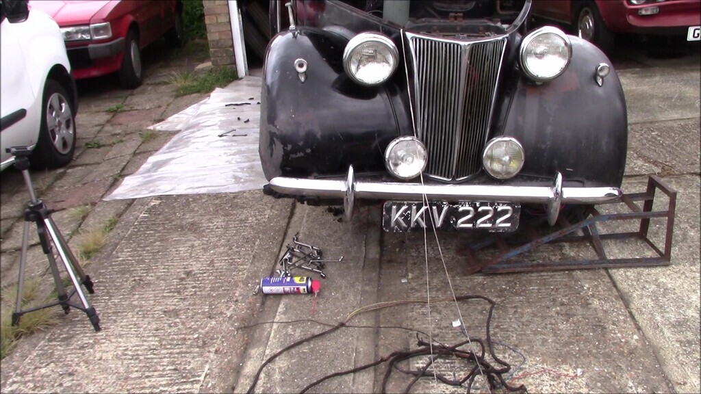
Thank you! It's a (old by today's standards) Canon Legria HFR706 on a Jessops telescopic aluminium tripod, both of which came to me second-hand. The Canon has pretty good image stabilisation, helped by the way you hold it with it being a long camcorder shape rather than a DSLR camera shape, so it's nicely balanced in the hand. It can be difficult to get in a space if I need to be in the space too, so sometimes I have to figure out work arounds and put the tripod in weird places. I want folks to be able to see as clearly as possible what's happening, and it's good to have that extra pair of eyes so I can watch back the footage and spot things I couldn't see when I was working on a job. The camera is a surprisingly useful tool with this work.
I noticed a good portion of viewers use the subtitles and I'm all about accessibility where possible so I make sure I type up what I'm actually saying rather than relying on the automatic subtitles. Sometimes it can be easy to misunderstand what I've said, or a word I've used, and hopefully the subtitles help clear any of that up. |
|
| Back to top |
|
|
peter scott
Joined: 18 Dec 2007
Posts: 7122
Location: Edinburgh
|
| Posted: Wed Apr 13, 2022 11:51 am Post subject: |
|
|
Thanks, That's very interesting.
Peter
_________________
http://www.nostalgiatech.co.uk
1939 SS Jaguar 2 1/2 litre saloon |
|
| Back to top |
|
|
Vulgalour
Joined: 08 May 2018
Posts: 474
Location: Kent
|
| Posted: Sat Apr 23, 2022 10:59 pm Post subject: |
|
|
I'm a little bit behind responding to messages etc. but I will get caught up with everything as time permits. House and cars and work and health all joined forces over the course of this month so I'm stretched a bit thin.
Tonight I finally got time to put a write-up together for the last Lanchester video for those that prefer. If you are curious about the wiring routing the video does explain it a bit better than this write up does. I will be doing a final wiring video when it's all done that will be easier to digest, it's just going to take some time to get to that point unfortunately, there's a fair bit of planning involved in that one.
----
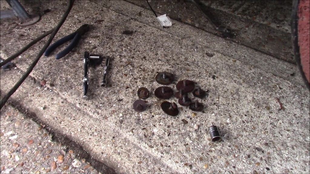
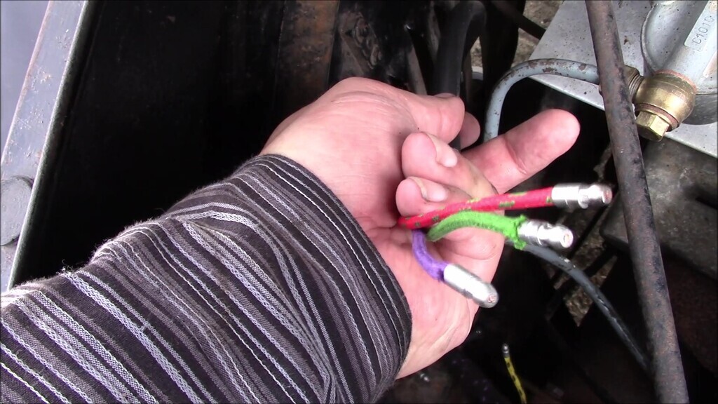
Quite an important one this for the project since it marks the point that all the old wiring is removed from the car. The little tails attached to items don't count, they're basically just labels so we know what things are at this point. The whole harness is as of this video finally out.
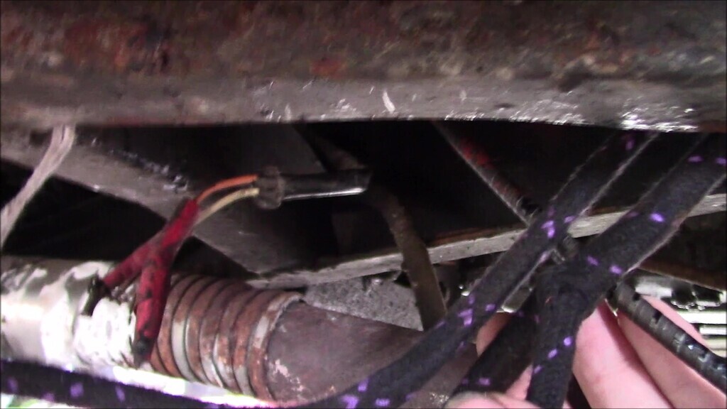
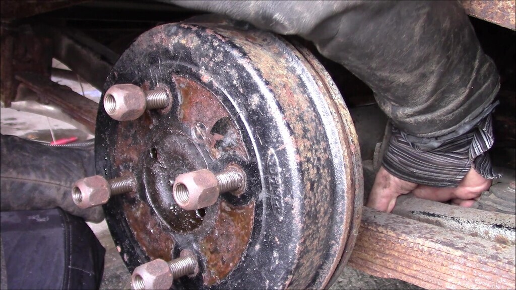
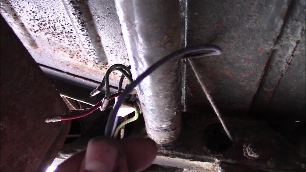
We'll start underneath the driver's seat where you can see the wires for the brake light switch. I snipped these off on the old loom side because I wasn't sure what was underneath the red electrical tape at this point and wanted to leave the longest wire I could on the switch side.
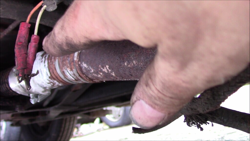
I'd already spent some time threading the old wiring through the chassis with string attached to the loose end so I had a return path established. Along the way I had to remove the wire clamps and I also had to work blind since you can't really see what you're doing without removing the body from the chassis or getting the car on a lift, neither of which were options for me.
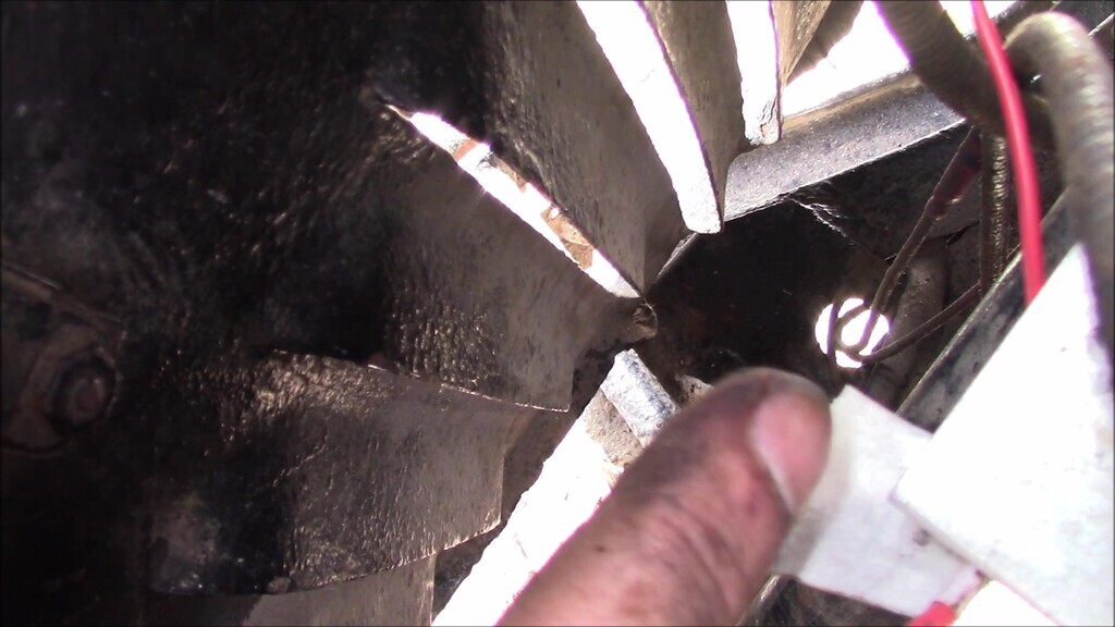
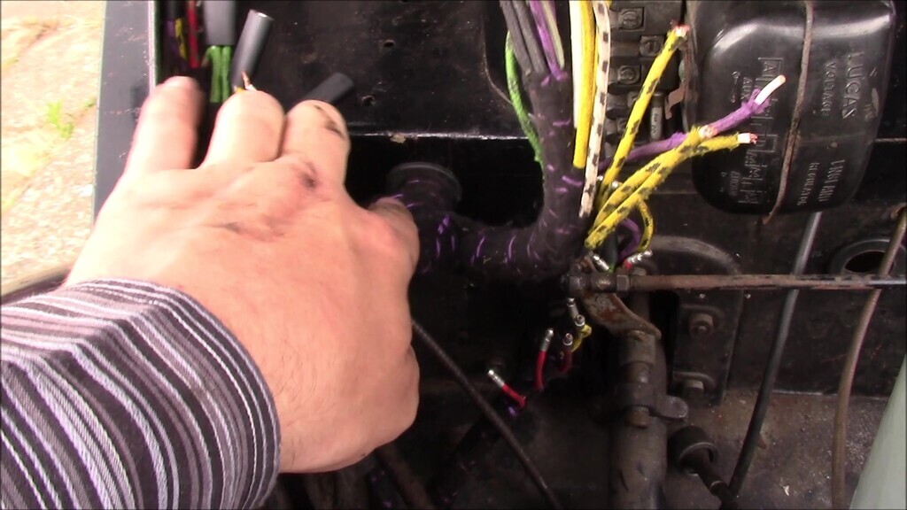
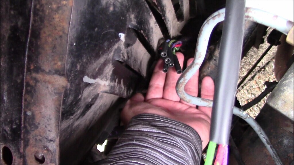
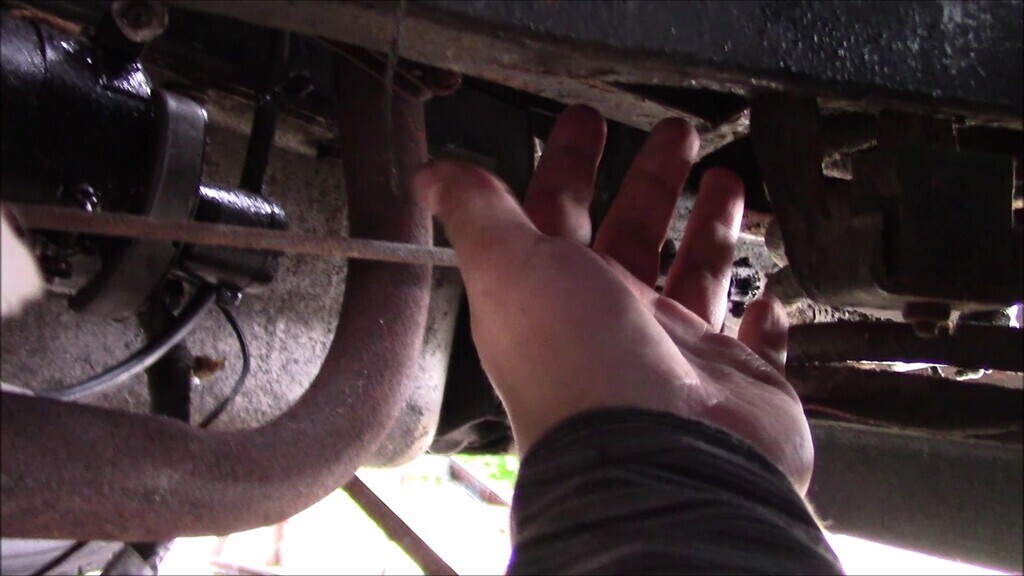
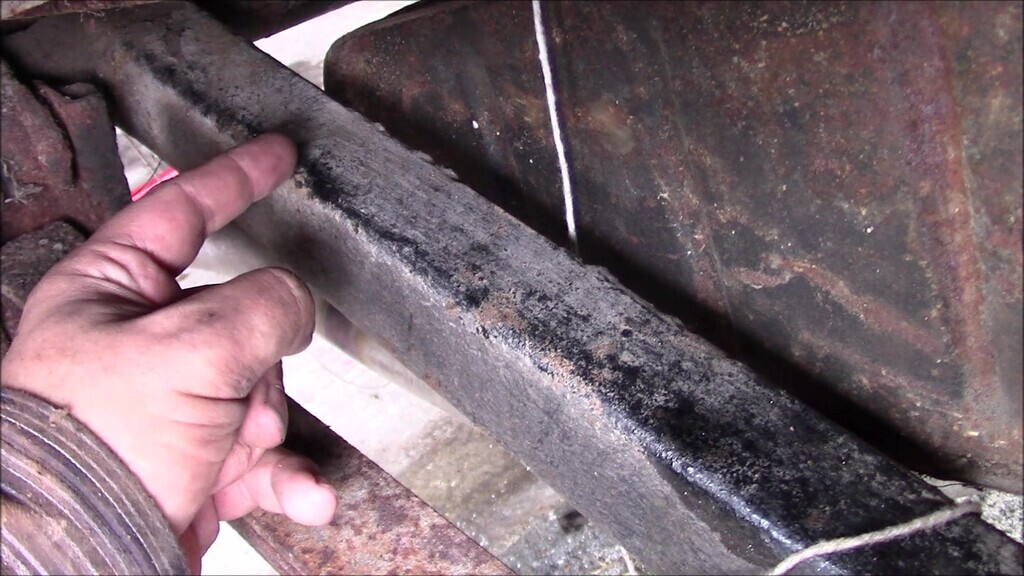
As I got to the A pillar, the chassis becomes totally boxed in so you can't see what you're doing even if it were a bare chassis. I needed to be able to access the back edge of the chassis before it became blind and the engine bay side of the top of the chassis, at the same time. Pat wasn't available to help so I'd have to partially dismantle things to do this. Where my hand is here is about where I needed to be on the other side of the inner arch. The gap where you see the blue wire coming out isn't big enough for me to get my hand through and into a place I need it to be to guide the arch.
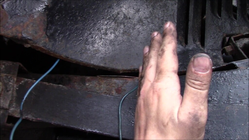
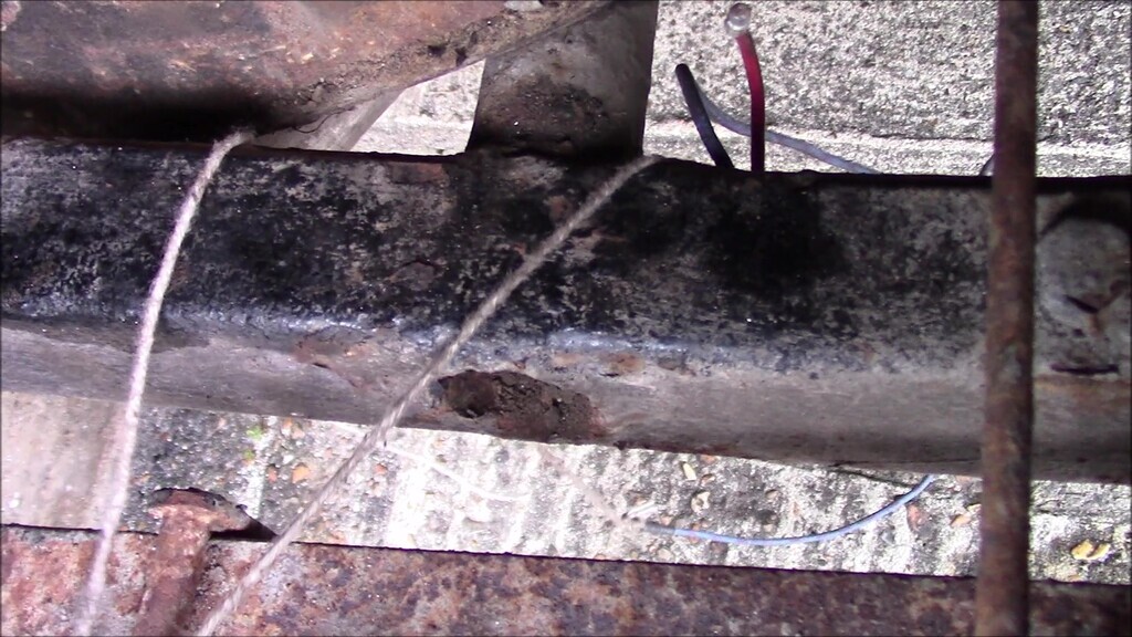
You can just see the two sections of wiring through the gap where they emerge out of the top of the chassis here.
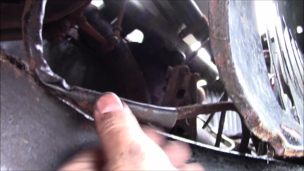
I removed pretty much all the inner arch fixings so I could finegle the panel out just enough to get my hand in for this job, I'll need to reassemble everything later. If you have the space to remove the inner and outer wing, I'd recommend it, and then leave them off until you've finished reassembling and testing everything. Unfortunately, I didn't the space to be storing removed panels at the time of recording, so I'm doing it this way.
I gradually fed the old wiring through until I had it all out and the strings in the path the old wiring took. That makes it sound a lot easier than it was.
The relief I had seeing the old wiring pulled out and in front of the car bordered on joy. This was one of those milestones where in theory at least, things should start getting better. This had ended up being a surprisingly grimy job to do.

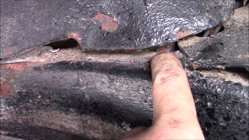
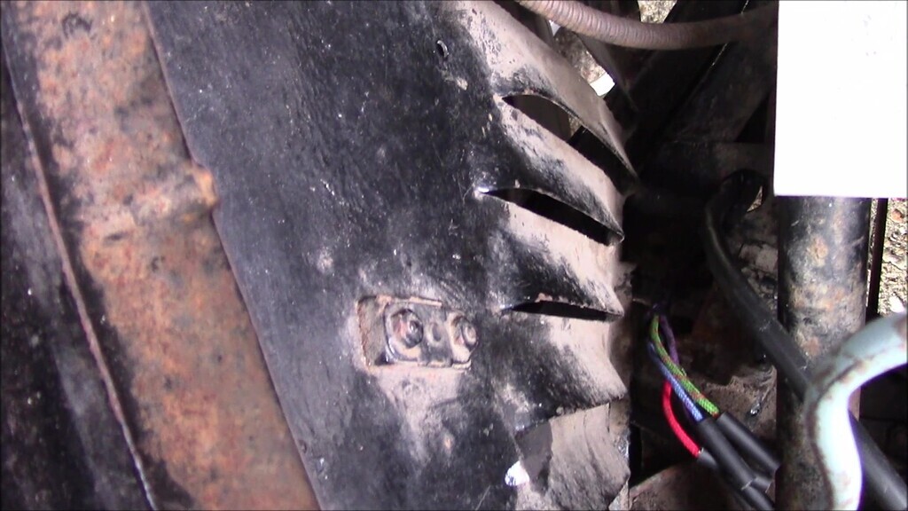
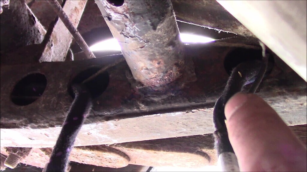
I did have to make a decision about the re-routing of the new wiring. Above you can see the strings go through a triangular and a round hole, one for each wiring section. I opted to put both through the round hole because I felt like they were less likely to chafe or get snagged on the corners of the triangular hole that way. I don't believe there should be a grommet here as there was no witness marks to suggest there ever had been one so I didn't put one in.
Back in the engine bay, a few things had finally been worked out. The main wiring in the cabing needs to be fed in from the engine bay side of the bulkhead through this point and finished with a large grommet. This grommet was provided with the wiring loom, so that's something. It had taken me quite a few attempts to figure out how to correctly route the wiring here, good old trial and error there.
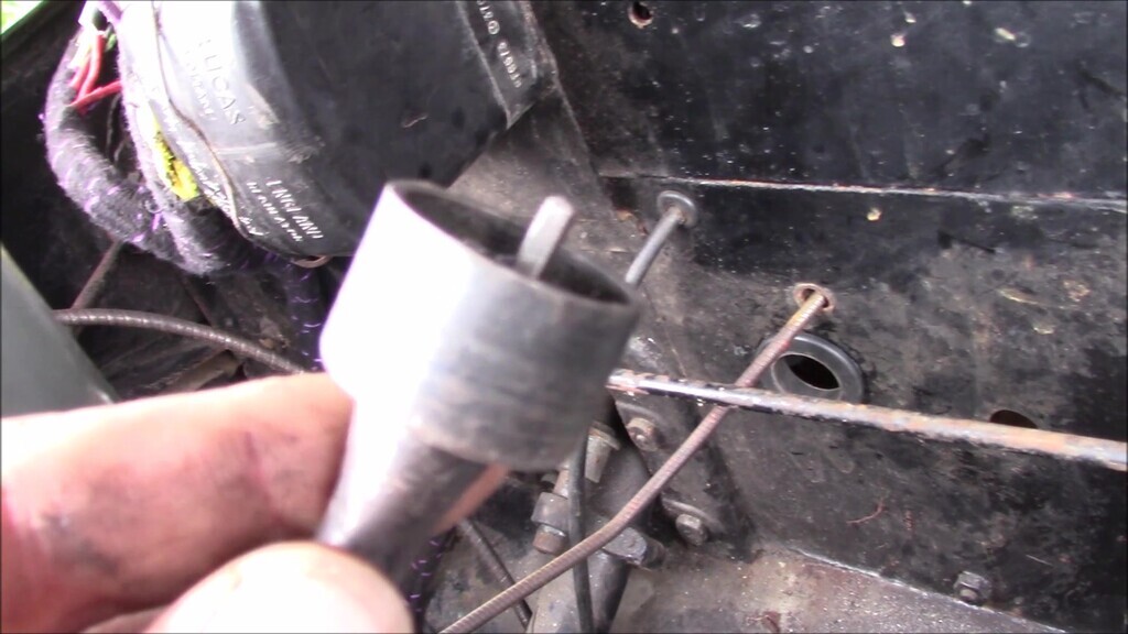
Similarly the speedo cable which has a hole in the bulkhead just large enough for the head of the cable to go through providing you remove the grommet first. I slid the grommet onto the cable before fitting. At the time of writing, I'm still not happy with the cable routing from the bulkhead to the gearbox so I'll be removing the gearbox end of the connector and seeing if I can resolve that, right now it just seems to be too loose and floppy and looks like it ought to run through or along the chassis to keep it secure.
I began feeding the new wiring through, using the strings as guides, with my only change being to run both sections through the round hole in the chassis. This made things quite tidy and didn't appear to put any strain or stress on anything. It was really nice to see new wires going in here.
I soon encountered my first issue, which was where the wiring enters the chassis, turns ninety degrees to go through a blind section, and then exits into the open section of the chassis. I found it easiest to feed each wire run in turn through the triangular hole here so I had some loose, then push it gradually through the chassis rail until it emerged in the open section where the chassis rails forked. Fiddly work.
once out, I could check the lengths were roughly correct by lining up the plastic sheathing on the new wiring in the engine bay with the amount of wire that would be exposed outside the chassis, and lining up the brake switch wiring spur roughly with the location of the brake switch under the drivers seat.
With that done it was a case of feeding and shuffling the new wire through the chassis rail, using the access holes on the inside to help and making sure the wire and string didn't get snagged in the narrow end of the guide brackets inside the chassis. Later I'll refit the wiring clamps once I'm sure it all works and everything is tested, no point doing it now since if I have to remove anything for any reason it would be one extra step I could do without. Once all the wiring was fed through and I'd got as far as the fuel tank at the back, the next challenge presented itself.
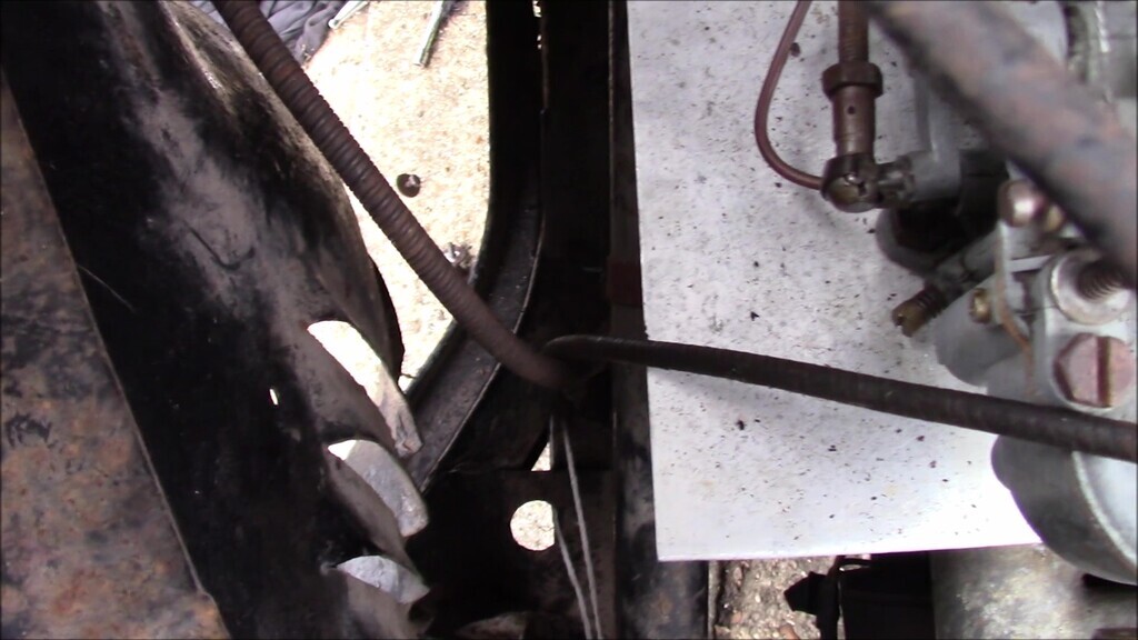
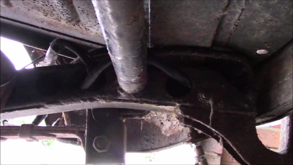
There's a cross beam in front of the fuel tank that the two separate wiring sections have to go around. Because of the way the chassis is built, you can't just thread the wiring down the whole length, it has to exit in front of the cross beam, loop over it, and re-enter the chassis behind it. The run with the fuel tank sender wire goes underneath, and the run without goes over the top.
When you've gone over-under the cross beam, the wiring has to re-enter the chassis and shuffle along until it gets to the cross beam behind the fuel tank where you do the same thing, only this time make sure the fuel sender wire doesn't go back into the chassis and instead goes along the cross beam to the fuel sender in the top of the tank.
The fuel sender wire wiring section doesn't re-enter the chassis, that comes out at the cross beam. The other wiring section does go through the chassis and doubles back. At least, that's how the original wiring ran on this car so I have to assume that's how it should be. Both wiring sections ended up where they should be in the end so hopefully it's correct.
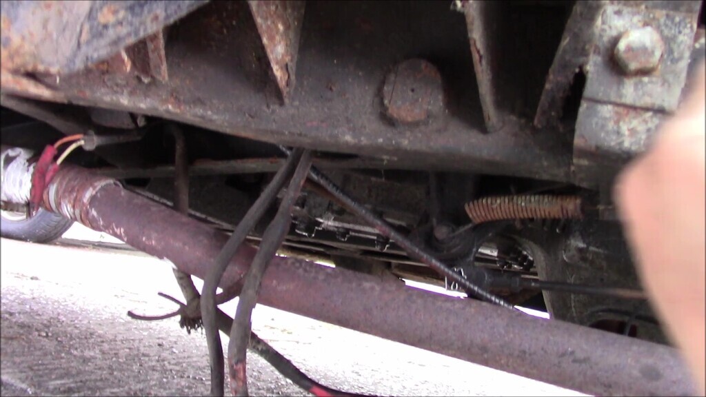
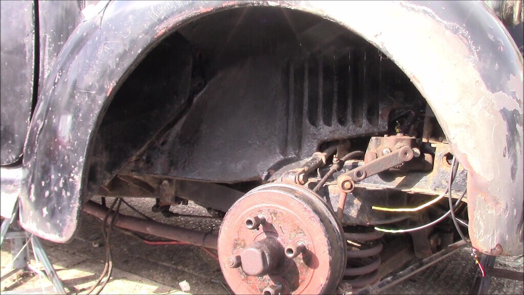
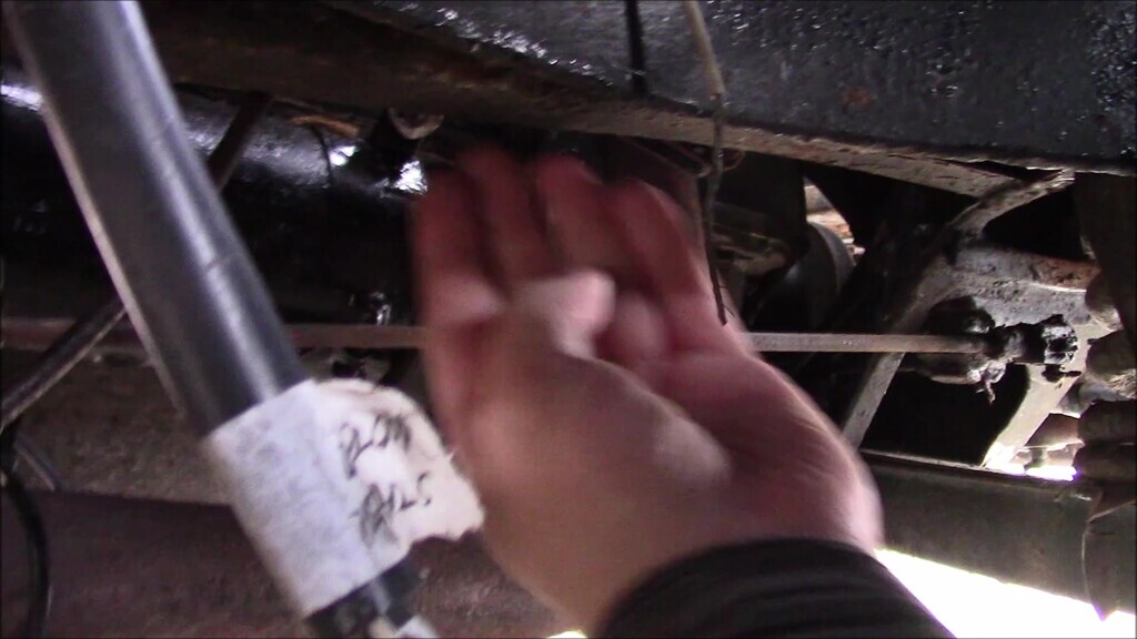
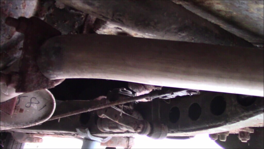
With all that done, when you look under the car the wiring is practically invisible now. Unless you know where to look for it, there's no obvious sign that it's there, which is what cause the initial confusion when trying to figure this one out. I'm used to wiring that runs inside a car, until this car I wouldn't have thought to look inside the chassis for it. A nice tidy job really.
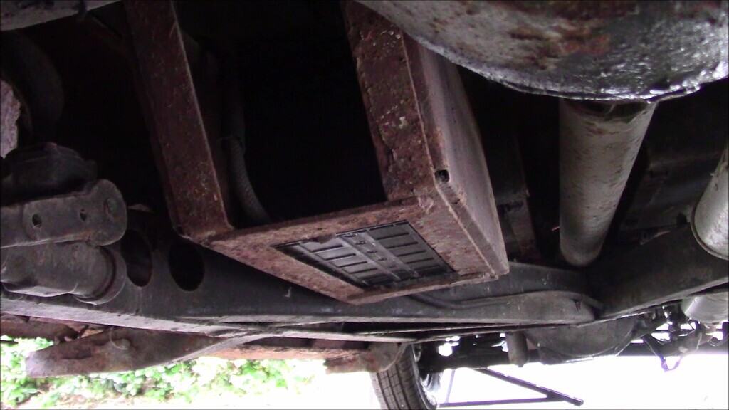
You can see here the really long battery cable that runs from the battery on the left of the image to the starter motor on the right. That's going to have to be a custom cable and one that I might get made rather than attempting to DIY since there are some jobs lately that I just want to give someone else some money to do for me. We shall see.
Our next Lanchester video instalment is on Tuesday the 26th of April, so tune in for that. The write-up for that will happen some time later. |
|
| Back to top |
|
|
Bitumen Boy
Joined: 26 Jan 2012
Posts: 1736
Location: Above the snow line in old Monmouthshire
|
| Posted: Sun Apr 24, 2022 12:18 pm Post subject: |
|
|
Compared to what you've done so far making up a new battery cable should be an refreshingly easy job as a reward for your patience so far. Length of cable, two ends, job done. Assuming you don't have the kit to crimp connectors to such heavy cable then solder works perfectly well.
Don't just chuck the old wiring, by the way - with what looks like a good length of the old battery cable as well it ought to get you a few £ for scrap  |
|
| Back to top |
|
|
Ray White

Joined: 02 Dec 2014
Posts: 6337
Location: Derby
|
| Posted: Sun Apr 24, 2022 12:30 pm Post subject: |
|
|
You might want to consider seeing what is available in terms of battery cables at your local scrap yard (if you have one). You never know what they might have salvaged.  |
|
| Back to top |
|
|
Miken
Joined: 24 Dec 2012
Posts: 544
|
| Posted: Sun Apr 24, 2022 6:25 pm Post subject: |
|
|
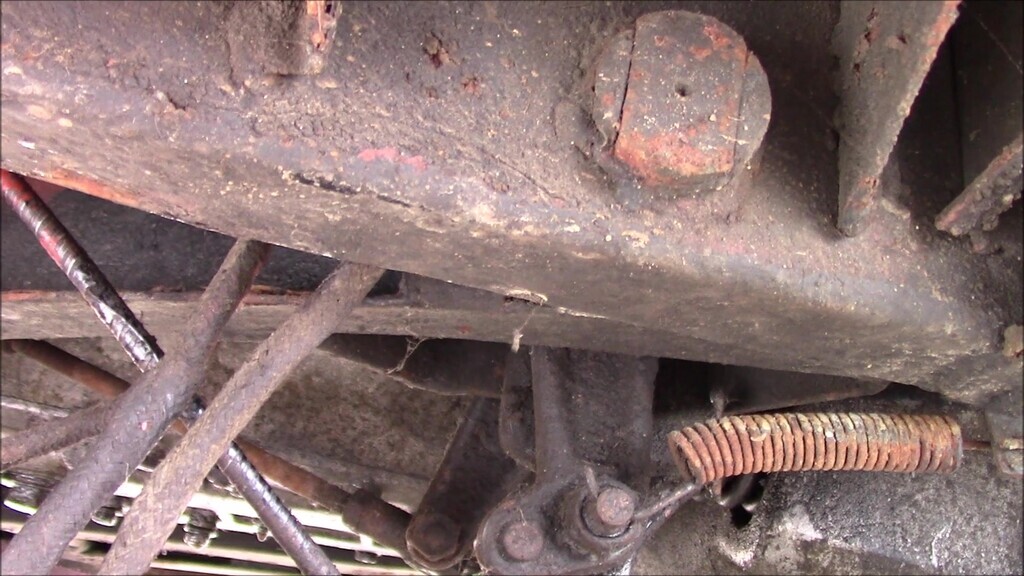
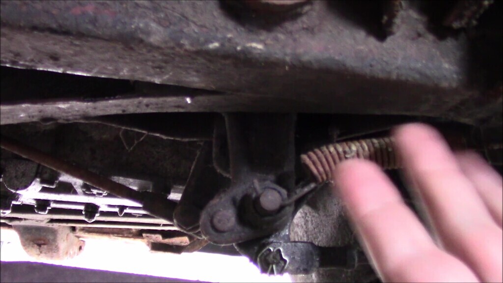
| Just an observation, I notice that the hook end of the tension spring on your brake (or clutch) pedal looks like it will Pull through without much trouble. |
|
| Back to top |
|
|
Ray White
Joined: 02 Dec 2014
Posts: 6337
Location: Derby
|
| Posted: Sun Apr 24, 2022 10:13 pm Post subject: |
|
|
| It all looks nice and solid under there. I would paint some rust converter on exposed areas. |
|
| Back to top |
|
|
Vulgalour
Joined: 08 May 2018
Posts: 474
Location: Kent
|
| Posted: Mon Apr 25, 2022 10:09 am Post subject: |
|
|
@Bitumen Boy: It's not that I can't do it, I just don't want to do it. Sometimes it's just nice to get someone else to do things.
@Ray White: I have no idea who our local scrapyard is, there must be one since we have plenty of visits from hopeful scrapmen here. I've not been to a scrapyard for ages.
@Miken: Brake pedal on that one I believe. Once the electrical is done, going over the underside and getting it all cleaned, re-greased, painted, and inspected is next. Nothing alarming has jumped out so we've left things alone up until now. You're right though, the hook on that spring does look very straight now you point it out. |
|
| Back to top |
|
|
Vulgalour
Joined: 08 May 2018
Posts: 474
Location: Kent
|
| Posted: Tue Apr 26, 2022 3:49 pm Post subject: |
|
|
As promised, a fresh video.
https://youtu.be/xBd9hteA7MA
Regular readers will remember the stress I had with trying to figure out the wiring on the car, the wiring provided, and the diagrams I was trying to work from. Hopefully this video explains a bit better what I was trying to communicate at the time and why it was quite so frustrating. Having the correct instructions really does make all the difference on a job like this. |
|
| Back to top |
|
|
Vulgalour
Joined: 08 May 2018
Posts: 474
Location: Kent
|
| Posted: Tue Apr 26, 2022 10:12 pm Post subject: |
|
|
With the help of the photos I took when I removed the horn/semaphore boss, and the useful guide over here: http://ld10.awardspace.co.uk/controls/control.htm I've been able to clean up the components and identify an issue.
Our horn push return spring is missing. This is the spring that prevents the horn button from making contact, quite why it's missing is a mystery. We need to find a replacement for it now.
It does make me wonder if the horns the car came to us with weren't working because the horn push had effectively been permanently connected and therefore burned them out. There's no random spring in the few spares that came with the car either.
Any suggestions on where I might acquire a horn button return spring are welcome, I'm not sure what size/ratings it should be since I don't have anything to go off here. |
|
| Back to top |
|
|
bjacko
Joined: 28 Oct 2013
Posts: 364
Location: Melbourne Australia
|
| Posted: Wed Apr 27, 2022 7:45 am Post subject: Lanchester 10 |
|
|
| I cannot tell you where to get one but I can tell you it is part number 322093, has about 4 coils and it is tapered i.e. one end the coils are larger than the other, and is 7/8" long. From Lucas parts list. |
|
| Back to top |
|
|
Miken
Joined: 24 Dec 2012
Posts: 544
|
| Posted: Wed Apr 27, 2022 10:59 pm Post subject: |
|
|
Your horn/semaphore boss looks suspiciously similar to the item on my A40.
You could contact Graham Potts of Potts Parts who has a large stock of used A40 spares and usually charges pocket money prices. Google him, He is in kent. |
|
| Back to top |
|
|
|
|
You cannot post new topics in this forum
You cannot reply to topics in this forum
You cannot edit your posts in this forum
You cannot delete your posts in this forum
You cannot vote in polls in this forum
|
php BB powered © php BB Grp.
|


