|
|
| Author |
Message |
Ray White

Joined: 02 Dec 2014
Posts: 6318
Location: Derby
|
 Posted: Thu Mar 03, 2022 2:31 pm Post subject: Direction indicators question Posted: Thu Mar 03, 2022 2:31 pm Post subject: Direction indicators question |
 |
|
My indicators switch is unusual in that it has a built in flasher unit. I have added a feed wire and wires to left and right indicators.
I have just the ONE warning light and need to know how to get it to work.
Can someone give me advice please.
I am concerned that if I fit both left and right wires to the one light it might not operate the flashers properly. |
|
| Back to top |
|
 |
Penman
Joined: 23 Nov 2007
Posts: 4758
Location: Swindon, Wilts.
|
|
| Back to top |
|
|
Ray White
Joined: 02 Dec 2014
Posts: 6318
Location: Derby
|
| Posted: Thu Mar 03, 2022 3:26 pm Post subject: |
|
|
I think the Lucas (SBP120) had a separate flasher unit.
I didn't realise that my "Starlite" switch had its own flasher unit 'built in' until I tried fitting indicators to my '26 Dodge Brothers tourer. The result was "interesting" but had me completely baffled.!!
I am thinking that if I fit the indicators wires from both sides to the one warning light the current will flow from the switch/ flasher unit into the light ... but will also energise the other side..so both sides will illuminate!!!
I don't really know what I am doing so any help would be appreciated. All I know is that I only have enough space for one warning light and have fitted it now ...so there is no going back.!
I imagine there is something I will need to do with a couple of diodes but I am not at all sure.... |
|
| Back to top |
|
|
ukdave2002
Joined: 23 Nov 2007
Posts: 4105
Location: South Cheshire
|
| Posted: Thu Mar 03, 2022 6:13 pm Post subject: |
|
|
Ray, if your indicator switch has 3 terminals, then its designed to have separate LH/RH waring lamps.
You could have just one warning lamp, connect to both the LH & RH switch outputs via a diode on each feed, that way left and right wont interfere with each other.
Dave |
|
| Back to top |
|
|
Ray White
Joined: 02 Dec 2014
Posts: 6318
Location: Derby
|
| Posted: Thu Mar 03, 2022 6:31 pm Post subject: |
|
|
| ukdave2002 wrote: | Ray, if your indicator switch has 3 terminals, then its designed to have separate LH/RH waring lamps.
You could have just one warning lamp, connect to both the LH & RH switch outputs via a diode on each feed, that way left and right wont interfere with each other.
Dave |
Yes there are three terminals. I have connected the feed to IG and two appropriate wires to L & R. To be honest, I didn't realise that I would need two warning lights until I came to connecting the wires. Then the scales fell from my eyes and I could see how I would need to make the wires 'one way' .
I have ordered two 5 amp diodes but I am completely in the dark about them. Fingers crossed.
https://www.ebay.co.uk/itm/181886105424 |
|
| Back to top |
|
|
Ray White
Joined: 02 Dec 2014
Posts: 6318
Location: Derby
|
| Posted: Thu Mar 03, 2022 6:49 pm Post subject: |
|
|
Would I be better soldering two tails together onto a connector straight onto the light? ... or have a length of wire from the light to the diodes; if so, how long should it be.?
Just to be sure >| is current flow >>>>>? |
|
| Back to top |
|
|
MVPeters

Joined: 28 Aug 2008
Posts: 822
Location: Northern MA, USA
|
| Posted: Fri Mar 04, 2022 6:06 pm Post subject: |
|
|
Ray - I may be missing something, but if you can follow this diagram you don't need any diodes. If you have a 3-pin flasher, use the third pin for the dashboard light. If you have a 2-pin, connect the dash light to the output.
>> left
IGN >>> flasher >>> dir switch |
| >> right
|
|>>>>dashboard light
_________________
Mike - MVPeters at comcast.net
2002 MINI Cooper 'S' |
|
| Back to top |
|
|
ukdave2002
Joined: 23 Nov 2007
Posts: 4105
Location: South Cheshire
|
| Posted: Fri Mar 04, 2022 6:17 pm Post subject: |
|
|
| MVPeters wrote: | Ray - I may be missing something, but if you can follow this diagram you don't need any diodes. If you have a 3-pin flasher, use the third pin for the dashboard light. If you have a 2-pin, connect the dash light to the output.
>> left
IGN >>> flasher >>> dir switch |
| >> right
|
|>>>>dashboard light |
Its not a 3 pin flasher, its a 3 pin flasher and switch, if Ray had a separate flasher your schematic would work.
Dave |
|
| Back to top |
|
|
Ray White
Joined: 02 Dec 2014
Posts: 6318
Location: Derby
|
| Posted: Sat Mar 12, 2022 10:06 pm Post subject: |
|
|
I am not doing very well with these indicators. I bought two diodes and soldered them to the wires going from the switch to the dashboard warning light as discussed. They don't work as I intended but I think it may be I got them too hot by soldering. I have read that they should only be attached at their ends and not along the length of the tail as I have done.
Could I have ruined them by over heating?
These are the diodes. Perhaps I need to get some more.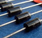
https://www.ebay.co.uk/itm/181886105424
Also I have not been able to get the flasher to work. I may have ruined the switch as well as something inside went bright. For all I know it might be a 6 volt switch but I thought the terminals were too small for 6 volt wires.
Everything is going pear shaped and I am out of my depth.  |
|
| Back to top |
|
|
ukdave2002
Joined: 23 Nov 2007
Posts: 4105
Location: South Cheshire
|
| Posted: Sun Mar 13, 2022 9:42 am Post subject: |
|
|
Hi Ray
electrically the diodes don't mind how long the tails are, you can test them with any multimeter, set to ohms, across the diode you will get current flow one way but not the other.
Regarding the switch, there is no such thing as a 6v or 12v rated switch, it the current that the switch will be rated at. As 6v systems require twice as much current as a 12v system, any switch used in 6v systems will be fine in the same 12v application.
Re the diodes you have got, they will work, but rated at 5A are far larger than you need to operate a panel lamp that will only draw mA's. If you need to get some more go for a 1N4001, they are my hack diodes for lowish current rectification, rated at 1A looing on eBay a pack of 10 is £1.50 posted to your door 
Dave |
|
| Back to top |
|
|
Ray White
Joined: 02 Dec 2014
Posts: 6318
Location: Derby
|
| Posted: Sun Mar 13, 2022 10:56 am Post subject: |
|
|
| ukdave2002 wrote: | Hi Ray
electrically the diodes don't mind how long the tails are, you can test them with any multimeter, set to ohms, across the diode you will get current flow one way but not the other.
Regarding the switch, there is no such thing as a 6v or 12v rated switch, it the current that the switch will be rated at. As 6v systems require twice as much current as a 12v system, any switch used in 6v systems will be fine in the same 12v application.
Re the diodes you have got, they will work, but rated at 5A are far larger than you need to operate a panel lamp that will only draw mA's. If you need to get some more go for a 1N4001, they are my hack diodes for lowish current rectification, rated at 1A looing on eBay a pack of 10 is £1.50 posted to your door
Dave |
Dave. I am thinking I might have ruined the diodes by the way I have soldered them by twisting the wire around the tail. Perhaps they have got too hot during soldering?
I will get some lower rated diodes and try again. (As it happens I couldn't get a multimeter current to pass either way through the 5 amp ones?)
One thing I don't know is how to test the switch. This one has a flasher unit built in and I was concerned the flasher may or may not have a voltage rating??
...and what about + or - earthing? |
|
| Back to top |
|
|
ukdave2002
Joined: 23 Nov 2007
Posts: 4105
Location: South Cheshire
|
| Posted: Sun Mar 13, 2022 11:07 am Post subject: |
|
|
Hi Ray
What do you mean by "twisting the wires around the tail"? I cant quite visualise it.
Dave |
|
| Back to top |
|
|
Ray White
Joined: 02 Dec 2014
Posts: 6318
Location: Derby
|
| Posted: Sun Mar 13, 2022 11:47 am Post subject: |
|
|
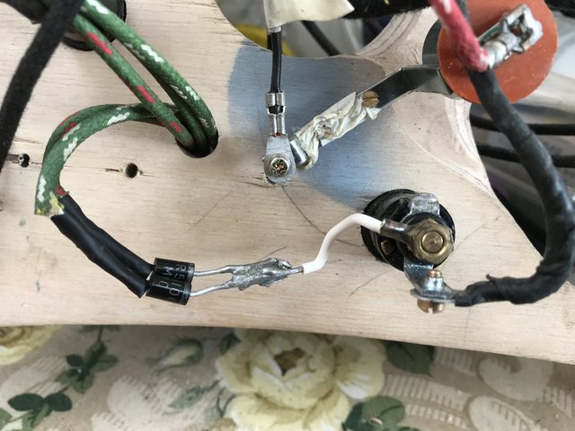
The left and right indicator wires from the switch (other side of wood) are now covered in heat shrink but they were pared back and the strands of copper wire wound around each diode tail and individually soldered. The tails before the light join the white wire and were all soldered together...
p.s. the earth wire looks like it is red/white .. but it is not. Just the way the photo came out. |
|
| Back to top |
|
|
ukdave2002
Joined: 23 Nov 2007
Posts: 4105
Location: South Cheshire
|
| Posted: Mon Mar 14, 2022 9:24 am Post subject: |
|
|
Hi Ray
The circuit looks correct assuming the car is negative earth. If the diodes have failed due to excess heat they could fail either open or short circuit, if they have failed short circuit then the current from one side of the turn indicator would be fed to the other side, I can't see why this would damage your switch, but need a schematic of the switch internals to confirm.
One other issue could be that the warning lamp is short circuit, in which case switching the indicators on could create some sparks! but hopefully just blow a fuse!
Dave |
|
| Back to top |
|
|
Ray White
Joined: 02 Dec 2014
Posts: 6318
Location: Derby
|
| Posted: Mon Mar 14, 2022 10:14 am Post subject: |
|
|
| ukdave2002 wrote: | Hi Ray
The circuit looks correct assuming the car is negative earth. If the diodes have failed due to excess heat they could fail either open or short circuit, if they have failed short circuit then the current from one side of the turn indicator would be fed to the other side, I can't see why this would damage your switch, but need a schematic of the switch internals to confirm.
One other issue could be that the warning lamp is short circuit, in which case switching the indicators on could create some sparks! but hopefully just blow a fuse!
Dave |
Dave the car is Positive Earth but the dash is on the bench and I am just wiring up and testing with a 6 volt battery. No fuse so probably asking for trouble.?
I have ordered some 1A diodes as suggested. The diodes are now de soldered and I am going back to square one.
To be honest I am well out of my comfort zone. Some might say out of my depth.  |
|
| Back to top |
|
|
|


