|
|
| Author |
Message |
Standard56
Joined: 26 Jun 2024
Posts: 162
Location: Victoria, Australia
|
 Posted: Sat Jul 06, 2024 1:39 pm Post subject: Morris 25 engine problems. Posted: Sat Jul 06, 2024 1:39 pm Post subject: Morris 25 engine problems. |
 |
|
Hi
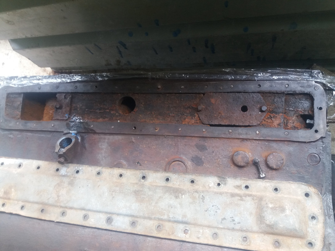
I have a few of these side valve 6 Morris engines with a 82mm bore . These engines were fitted in the Morris 25 car up to 1938 and in some of the MCC trucks as well as the military Morris-Commercial CS8 truck.
During the strip down of a engine , the thirtytwo (32) M6 side cover bolts became a problem..... well most of them broke despite soaking for a long period. The M6 bolts are rather stuck after 70 + years and they are fragile little things.
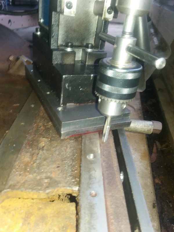
I decided to drill out the broken M6 bolts and install helicoils. This has been a exercise in precision drilling. I made up a little guide or jig to locate the drill on centre in the broken bolts.
My jig has worked pretty well but this type of job it is always a risky undertaking and one never knows what the final outcome will be. At least I can say that I tried something, the other alternative was to junk the engine
 |
|
| Back to top |
|
 |
Bitumen Boy
Joined: 26 Jan 2012
Posts: 1763
Location: Above the snow line in old Monmouthshire
|
| Posted: Sat Jul 06, 2024 8:00 pm Post subject: |
|
|
That's an unusual design with all those little bolts, I'm guessing the cover is pretty thin sheet steel? Well done for having a go at it, look forward to hearing more  |
|
| Back to top |
|
|
peter scott

Joined: 18 Dec 2007
Posts: 7223
Location: Edinburgh
|
| Posted: Sat Jul 06, 2024 8:39 pm Post subject: |
|
|
Tricky job. Well done tackling it.
Peter
_________________
https://www.nostalgiatech.co.uk
1939 SS Jaguar 2 1/2 litre saloon |
|
| Back to top |
|
|
Standard56
Joined: 26 Jun 2024
Posts: 162
Location: Victoria, Australia
|
| Posted: Sun Jul 07, 2024 4:22 am Post subject: Drilling |
|
|
Thanks for the comments. Yes the cover is a thin aluminium pressed sheet.
If anybody is going to attempt this type of repair, I have a few tips:
Very important: Use sharp drills and drill in .5mm steps . I begin with a centre or spot drill , then I go to a 4mm drill and continue up to the 6.3mm drill that is supplied in the heli-coil kit.
The heli-coil tap will last for about ten holes, you then need to sharpen the cutting edges of the tap with a small curved honing stone OR buy a new tap. You will risk breaking a tap if you use a dull tap.
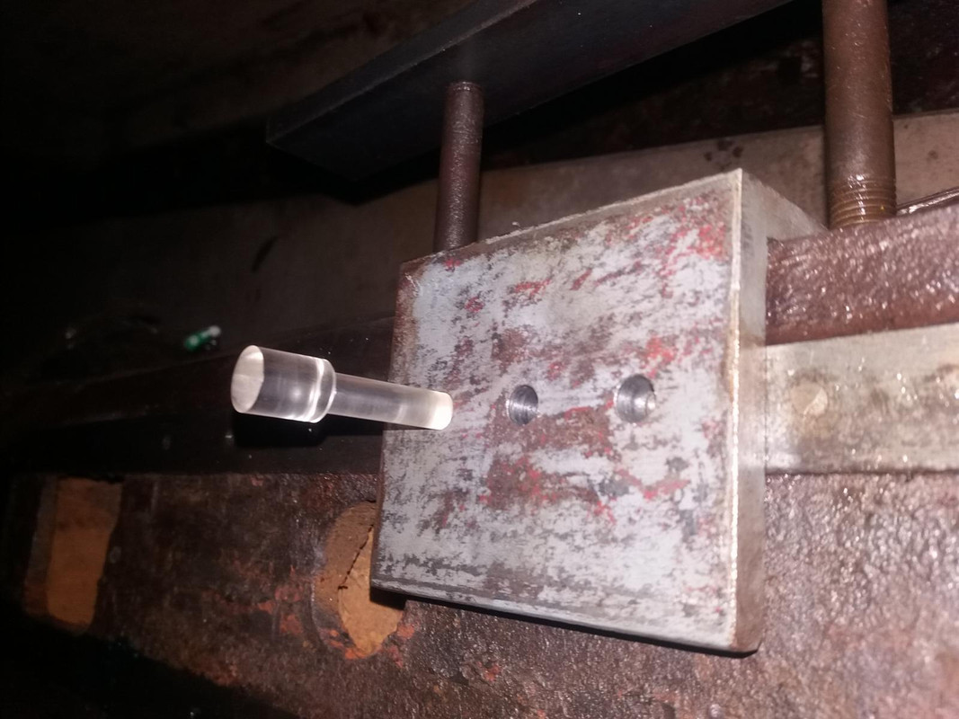
I used a cheap mag-drill , the drill needs to be accurately aligned and straight. I made a little jig that accepts a optical aligner , it has cross hairs. After centreing the 8mm optical device, I use a 8mm precision gauge in the drill chuck to align the drill in the hole.
The original holes drilled by Morris Motors factory are slightly out of alignment: by as much as .3mm. So I adjust the alignment of the jig by inserting shims behind the face that sits on the engine top.
The alignment jig needs to be fixed firmly , if it moves around it will result in misalignment of the drill. I made up a bar that is drilled to the correct spacing to fit over two of the head studs, this bar clamps down onto the jig.
Removing the head studs is another problem. I managed to do it , I will make another post about this !
 |
|
| Back to top |
|
|
Ray White

Joined: 02 Dec 2014
Posts: 7319
Location: Derby
|
| Posted: Sun Jul 07, 2024 8:47 am Post subject: |
|
|
| So what I assume you are doing is correctly fitting a cover to the side of the water jacket. I notice that in addition to a round hole there are two rectangular plated holes; one seems to be broken. What are these for, please? |
|
| Back to top |
|
|
bjacko
Joined: 28 Oct 2013
Posts: 551
Location: Melbourne Australia
|
| Posted: Sun Jul 07, 2024 8:49 am Post subject: Morris 25 Engine Side Panel |
|
|
I have not heard of a bolt problem before but the side panel becoming holed by rust is common. one person I know with the same engine in a Wolsely fitted a stainless steel panel.
_________________
1938 Morris 8 Ser II Coupe Utility (Pickup)
1985 Rover SD1 VDP |
|
| Back to top |
|
|
Standard56
Joined: 26 Jun 2024
Posts: 162
Location: Victoria, Australia
|
| Posted: Sun Jul 07, 2024 10:32 am Post subject: Holes |
|
|
| Ray White wrote: | | So what I assume you are doing is correctly fitting a cover to the side of the water jacket. I notice that in addition to a round hole there are two rectangular plated holes; one seems to be broken. What are these for, please? |
Yes I am repairing the original threaded holes so that I can fit the original side cover back on.
That is a good question: you ask about the rectangular holes and the rusty covers. The rectangular holes are passages to allow for the coolant to flow into the internals. I think the rusty (broken) covers are placed there to regulate or control the coolant flow. This engine I am working on is a wartime built engine from 1940 , it was fitted to a military CS8 truck.
I also have a earlier civilian engine from a 1937 MCC truck and that engine has the whole of the side exposed or open . I believe they may have had some problems ( may have been stress cracks ) with the completely open side and they redesigned the shape of the side , closed it off, this was done to achieve a overall stronger engine block.
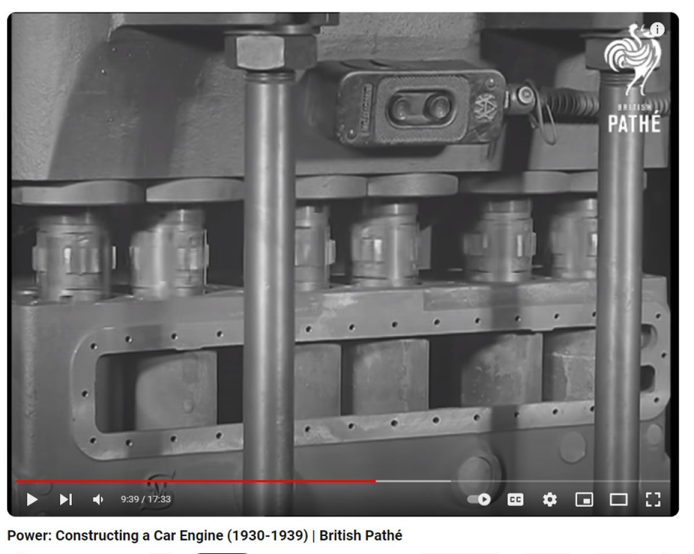
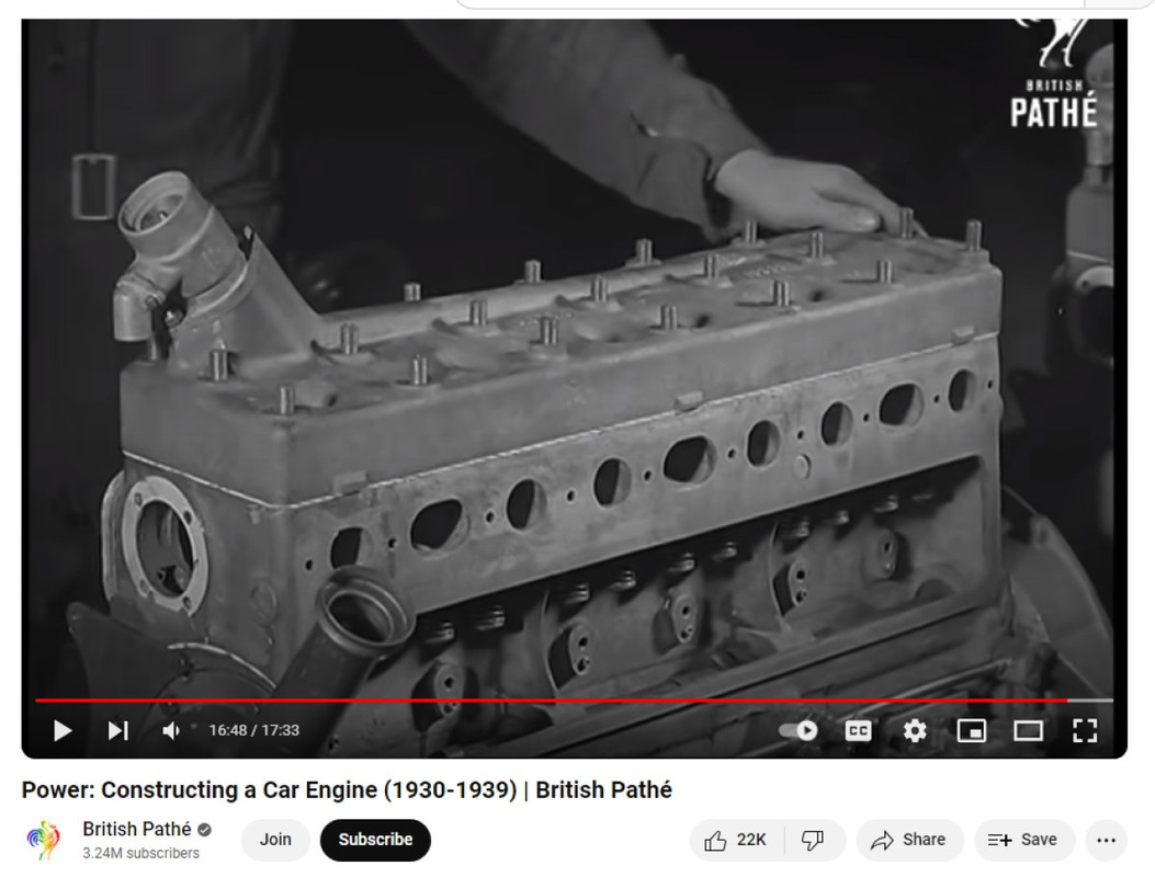
I found a pre-war film made by Morris Motors , it has a few scenes with the Morris 6 engine and how they drilled the 32 side cover holes in one operation !
Last edited by Standard56 on Thu Jul 11, 2024 9:49 am; edited 1 time in total |
|
| Back to top |
|
|
Ray White
Joined: 02 Dec 2014
Posts: 7319
Location: Derby
|
| Posted: Sun Jul 07, 2024 11:12 am Post subject: |
|
|
| I am interested to know if there are other metric sizes used by Morris on that engine.? When they took over Hotchkiss they found their tooling employed an obsolete metric thread with just 1 degree of pitch. (Modern metric has 1.25 or 1.5 deg.). Is this one of those engines? |
|
| Back to top |
|
|
Standard56
Joined: 26 Jun 2024
Posts: 162
Location: Victoria, Australia
|
| Posted: Mon Jul 08, 2024 6:18 am Post subject: |
|
|
| Ray White wrote: | | I am interested to know if there are other metric sizes used by Morris on that engine.? When they took over Hotchkiss they found their tooling employed an obsolete metric thread with just 1 degree of pitch. (Modern metric has 1.25 or 1.5 deg.). Is this one of those engines? |
Yes as far as I can determine, this Morris 25 engine has Metric dimensions for all of the bolts. The head studs are 12mm with a 1.5 pitch thread. Some of the bolt heads are larger than are used today, maybe this was done in order to fit the spanners they were using.
The little 6mm threads that I am repairing , they have a 1mm pitch - this seems to be a common pitch for the 6mm bolts, the hardware stores here sell 6mm X 1mm pitch bolts and screws.
There is a Metric standard for fine and coarse threads but Morris used some odd sizes . The Morris CS8 truck parts book has a list of the bolt sizes and thread pitch.
I was surprised to learn that the Hotchkiss company founder was a US citizen http://www.m201.com/hotchkiss/hotchkis.htm |
|
| Back to top |
|
|
bjacko
Joined: 28 Oct 2013
Posts: 551
Location: Melbourne Australia
|
| Posted: Mon Jul 08, 2024 7:33 am Post subject: Morris Engines |
|
|
All engines built in the Morris factory have metric threads and the nuts and bolts have British BSF.BSW spanner sizes, The gearboxes are the same. As above it was after they took over the Hotchkiss factory after WW1 as Hotchkiss had moved to UK early in the war. The tooling was all Metric and Morris decided to keep costs down by utilising it and to save mechanics buying new spanners got the hardware made with UK spanner sizes.
The parts attached to brackets on the engine are BSF with the bracket attached to the engine with metric threads e.g. generator. The gearbox was originally attached to the engine with metric bolts but "ace mechanics" believe these bolts with UK spanner sizes are BSF and many cars have dodgy threads.
The brake system units are USA threads because Lockheed is an American company. even though the parts were made in UK,
Most of the electrical system parts use BA threads.
Wolseley engines made in the Wolseley factory have UK threads including the 1930's minor overhead cam engines.
_________________
1938 Morris 8 Ser II Coupe Utility (Pickup)
1985 Rover SD1 VDP |
|
| Back to top |
|
|
Standard56
Joined: 26 Jun 2024
Posts: 162
Location: Victoria, Australia
|
| Posted: Mon Jul 29, 2024 3:05 am Post subject: Success |
|
|
I have finished this tricky job !
I drilled out the many broken bolts and then tapped in new threads to accept the heli-coils . I coated the heli-coil inserts with some Permatex sealant.
Now I have to do a slow boring job: machine up some new bolts , 32 of them. The little original M6 bolts have a oversized head to accept the 3/16 BSW spanners. I will use 8mm bolts (these have a larger head) and machine the M8 bolts down to 6mm and use a split die to rethread them. The larger heads will also help to seal the side cover gasket. |
|
| Back to top |
|
|
bjacko
Joined: 28 Oct 2013
Posts: 551
Location: Melbourne Australia
|
| Posted: Mon Jul 29, 2024 6:49 am Post subject: Morris Metric Hardware |
|
|
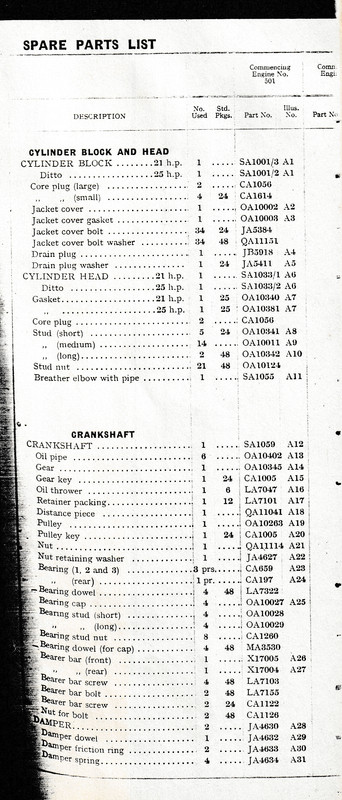
The hardware Morris used 5mm and 6mm were 1mm pitch, and 8mm 10mm, 12mm, 14mm were 1.5mm pitch.
The cylinder head studs were 2 long, 14 medium and 5 short in length.
The 24 side panel bolts were 8mm 1.5mm pitch with 2 washers each.
The Morris parts list only shows Morris reference part numbers not general hardware part numbers and they do not show threads, diameters, lengths or head types etc.
8mm X 1.5mm pitch are still available from bolt suppliers. (at least in Aus)
_________________
1938 Morris 8 Ser II Coupe Utility (Pickup)
1985 Rover SD1 VDP |
|
| Back to top |
|
|
Standard56
Joined: 26 Jun 2024
Posts: 162
Location: Victoria, Australia
|
| Posted: Mon Jul 29, 2024 12:08 pm Post subject: Re: Morris Metric Hardware |
|
|
| bjacko wrote: | The hardware Morris used 5mm and 6mm were 1mm pitch, and 8mm 10mm, 12mm, 14mm were 1.5mm pitch.
The cylinder head studs were 2 long, 14 medium and 5 short in length.
The 24 side panel bolts were 8mm 1.5mm pitch with 2 washers each.
The Morris parts list only shows Morris reference part numbers not general hardware part numbers and they do not show threads, diameters, lengths or head types etc.
8mm X 1.5mm pitch are still available from bolt suppliers. (at least in Aus) |
Hi
I guess the bolts are different for each type of Morris engine i.e. the 32 side cover bolts on the Morris 25 6 cyl. engines are 6mm x 1mm pitch.
The cyl. head bolts are all the same length and are 12mm X 1.5mm pitch.
The parts book I am using (for the Morris-Commercial CS8) has a appendix , it is a detailed list of the bolts with dimensions and pitches / lengths . |
|
| Back to top |
|
|
bjacko
Joined: 28 Oct 2013
Posts: 551
Location: Melbourne Australia
|
| Posted: Wed Jul 31, 2024 8:05 am Post subject: Morris 25 Engines |
|
|
The CS8 engine must be different to the Morris motors Parts catalogue. The head studs usually depend on what is attached to the studs on top of the head e.g. generator mounting bracket.
 [/img] [/img]
_________________
1938 Morris 8 Ser II Coupe Utility (Pickup)
1985 Rover SD1 VDP |
|
| Back to top |
|
|
Standard56
Joined: 26 Jun 2024
Posts: 162
Location: Victoria, Australia
|
| Posted: Thu Aug 08, 2024 10:08 am Post subject: Re: Morris 25 Engines |
|
|
[quote="bjacko"]The CS8 engine must be different to the Morris motors Parts catalogue. The head studs usually depend on what is attached to the studs on top of the head e.g. generator mounting bracket.
Yes I can see the three different stud lengths in that list that you attached. Interesting that the 25 sedan used a different head stud arrangement when compared to the Morris-Commercial trucks that had the 25hp engine fitted.
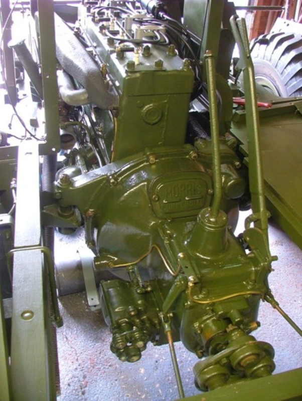
The CS8 engine has only the small thin bracket for the tube that the ignition leads go through, it fits over two of the head studs. The generator is driven internally by the timing chain.
I will have a look a the CS8 parts book.
I found a pic of a CS8 engine , a guy in the UK restored a CS8 radio truck. He has fitted some kind of strange ignition lead brackets that I have never seen before ? It might be for a screened ignition system. This is the main page https://www.fareham-darc.co.uk/G8KZO/CS8/CS8.htm
 |
|
| Back to top |
|
|
|


